Tools Required
J 25025 Guide Pins
Removal Procedure
- Raise the vehicle. Refer to Lifting and Jacking the Vehicle .
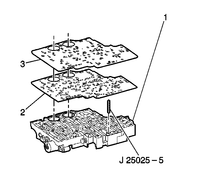
- Remove the control valve body assembly. Refer to Valve Body and Pressure Switch Replacement .
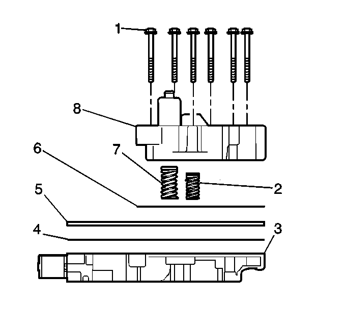
- Remove the 3rd and 4th clutch accumulator housing bolts (1).
- Remove the 3rd and 4th clutch accumulator housing (8).
- Remove the accumulator housing gasket (6). The accumulator housing gasket may be stuck to the spacer plate (5).
- Remove the 3rd clutch accumulator piston spring (7).
- Remove the 4th clutch accumulator piston spring (2).
- Remove the control valve body spacer plate (5).
- Remove the control valve assembly to spacer plate gasket (4) from the spacer plate (5).
Third and Fourth Clutch Accumulator Disassembly
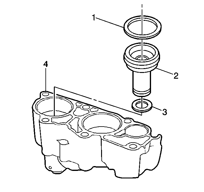
- Remove the 3rd clutch accumulator piston (2).
- Remove the 3rd clutch accumulator piston seals (1, 3).
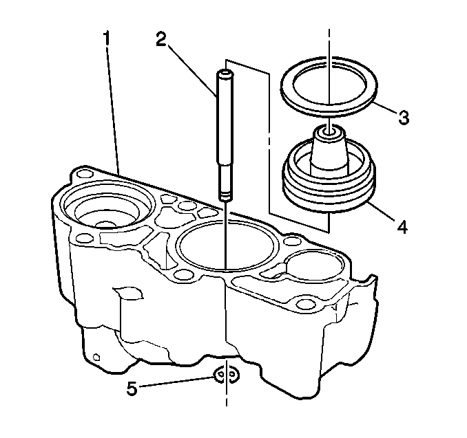
- Remove the 4th clutch accumulator piston pin retainer ring (5).
- Remove the 4th clutch accumulator piston (4) and pin (2) from the accumulator housing (1).
- Remove the 4th clutch accumulator piston pin (2) from the accumulator housing (1).
- Remove the 4th clutch accumulator piston seal (3) from the accumulator housing (1).
Important: Apply low pressure compressed air to the hole at the top of the accumulator housing to assist with the piston removal.
Third and Fourth Clutch Accumulator Assembly
- Install the 3rd clutch accumulator piston inner (3) and outer (1) seals. Lubricate the 3rd clutch accumulator piston seals (1, 3) with DEXRON® VI automatic transmission fluid.
- Install the 3rd clutch accumulator piston (2).
- Install the 4th clutch accumulator piston seal (3). Lubricate the 4th clutch accumulator piston seal (3) with DEXRON® VI automatic transmission fluid.
- Assemble the 4th clutch accumulator piston pin (2) with the 4th clutch accumulator piston (4).
- Install the 4th clutch accumulator piston assembly into the accumulator housing (1).
- Install the 4th clutch accumulator piston pin retainer ring (5) onto the 4th clutch accumulator piston pin (2).
Installation Procedure
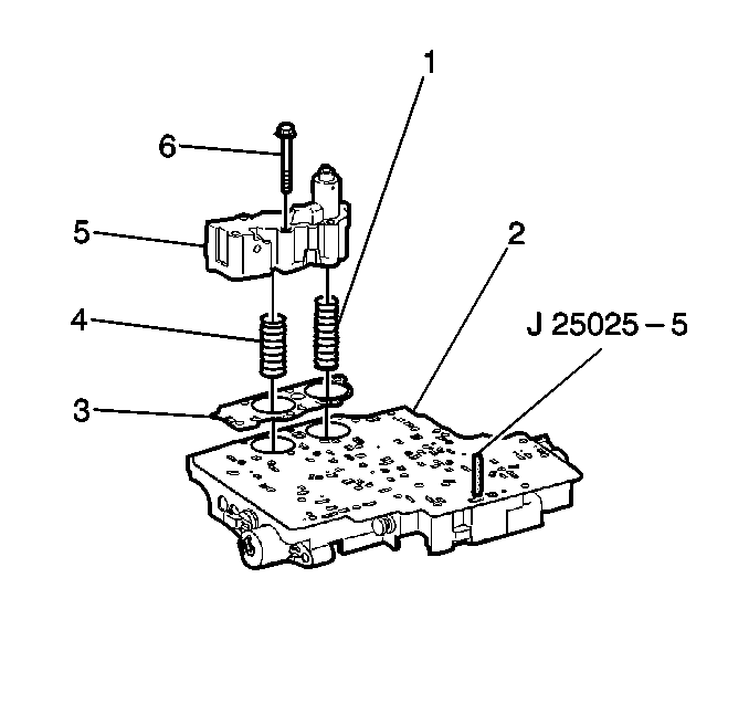
- Install the J 25025 into the control valve body bolt hole where the manual shaft detent roller and spring assembly is mounted.
- Install the control valve body gasket (2) onto the accumulator housing (1).
- Install the control valve body spacer plate (3) onto the valve body gasket (2).
- Install the third and fourth clutch accumulator housing gasket (3).
- Install the third clutch accumulator piston spring (1). This spring is the longer of the two springs.
- Install the fourth clutch accumulator piston spring (4).
- Install the third and fourth clutch accumulator housing assembly (5) onto the control valve body assembly (2).
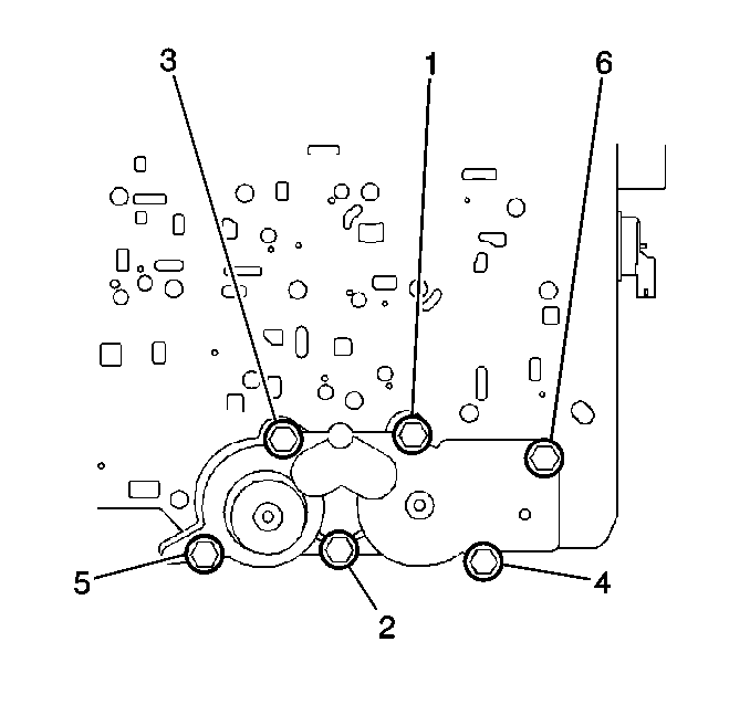
- Install the six accumulator housing bolts (6). Start the bolts finger tight and work towards the opposite end.
- Tighten the accumulator housing bolts sequentially.
- Remove the J 25025 .
- Install the control valve body assembly. Refer to Valve Body and Pressure Switch Replacement .
- Lower the vehicle.
- Fill the transmission to the proper level with DEXRON® VI transmission fluid. Refer to Transmission Fluid Check .
- Reset the TAP values. Refer to Transmission Adaptive Functions .
Notice: Use the correct fastener in the correct location. Replacement fasteners must be the correct part number for that application. Fasteners requiring replacement or fasteners requiring the use of thread locking compound or sealant are identified in the service procedure. Do not use paints, lubricants, or corrosion inhibitors on fasteners or fastener joint surfaces unless specified. These coatings affect fastener torque and joint clamping force and may damage the fastener. Use the correct tightening sequence and specifications when installing fasteners in order to avoid damage to parts and systems.
Tighten
Tighten the accumulator housing bolts to 11 N·m (97 lb in).
Important: It is recommended that transmission adaptive pressure (TAP) information be reset.
Resetting the TAP values using a scan tool will erase all learned values in all cells. As a result, The ECM, PCM or TCM will need to relearn TAP values. Transmission performance may be affected as new TAP values are learned.