Heater Case Replacement C60
Tools Required
| • | J 38185 Hose Clamp Pliers |
| • | J 39400-A Halogen Leak Detector |
Removal Procedure
- Drain the engine coolant. Refer to Cooling System Draining and Filling in Engine Cooling.
- Recover the refrigerant. Refer to Refrigerant Recovery and Recharging .
- Using the J 38185 reposition the heater hose clamps from the heater core.
- Remove the heater hoses from the heater core.
- Remove the evaporator case from the vehicle. Refer to Air Conditioning Evaporator Core Replacement .
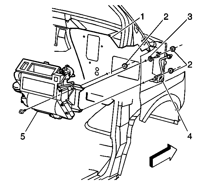
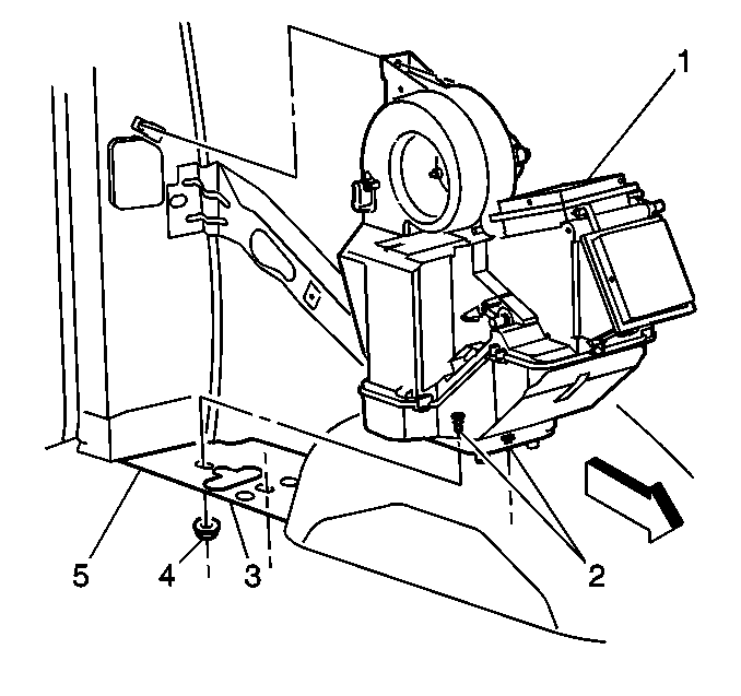
- Remove the heater case retaining nuts (2) from the engine compartment.
- Roll out the instrument panel. Refer to Instrument Panel Carrier Replacement in Instrument Panel, Gages and Console.
- Disconnect the electrical connectors.
- Disconnect the vacuum lines.
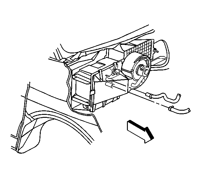
- Remove the heater case (5) from the vehicle.
Installation Procedure
- Install the heater case (5) to the vehicle.
- Connect the vacuum lines.
- Connect the electrical connectors.
- Roll the instrument panel upward. Refer to Instrument Panel Carrier Replacement in Instrument Panel, Gages and Console.
- Install the heater case retaining nuts (2) to the engine compartment.
- Install the evaporator casing to the vehicle. Refer to Air Conditioning Evaporator Core Replacement .
- Connect the heater hoses to the heater core.
- Using the J 38185 reposition the heater hose clamps to the heater core.
- Evacuate and recharge the A/C system. Refer to Refrigerant Recovery and Recharging .
- Leak test the fittings of the component using the J 39400-A .
- Fill the engine coolant. Refer to Cooling System Draining and Filling in Engine Cooling.
Notice: Use the correct fastener in the correct location. Replacement fasteners must be the correct part number for that application. Fasteners requiring replacement or fasteners requiring the use of thread locking compound or sealant are identified in the service procedure. Do not use paints, lubricants, or corrosion inhibitors on fasteners or fastener joint surfaces unless specified. These coatings affect fastener torque and joint clamping force and may damage the fastener. Use the correct tightening sequence and specifications when installing fasteners in order to avoid damage to parts and systems.
Tighten
Tighten the nuts to 6 N·m (53 lb in).
Heater Case Replacement C69
Removal Procedure
- Drain the engine coolant. Refer to Cooling System Draining and Filling in Engine Cooling.
- Recover the refrigerant, if equipped with A/C. Refer to Refrigerant Recovery and Recharging .
- Remove the left rear quarter trim panel. Refer to Body Side Rear Trim Panel Replacement in Interior Trim.
- Remove the left rear corner garnish molding . Refer to Body Rear Corner Garnish Molding Replacement in Interior Trim.
- Disconnect the heater air outlet ducts from the auxiliary heater. Refer to Auxiliary Air Outlet Duct Replacement .
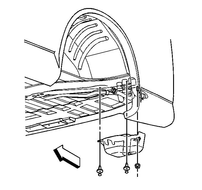
- Disconnect the electrical connectors from the auxiliary heater (1).
- Raise the vehicle. Support the vehicle with safety stands.
- Remove the heater and A/C line cover from the underside of the auxiliary heater.
- Remove the one retaining nut in order to remove the auxiliary evaporator underbody rear tube assembly from the core, if equipped.
- Disconnect the heater lines from the underside of the auxiliary heater.
- Remove the retaining nuts from the underside of the auxiliary heater.
- Remove the safety stands.
- Lower the vehicle.
- Remove the auxiliary heater from the vehicle.
Installation Procedure
- Install the auxiliary heater into the vehicle.
- Raise the vehicle. Support the vehicle with safety stands.
- Install the retaining nuts to the underside of the auxiliary heater.
- Connect the heater lines to the underside of the auxiliary heater.
- Install the one retaining nut to the auxiliary evaporator underbody rear tube assembly to the core, if equipped.
- Install the heater and heater line cover to the underside of the auxiliary heater.
- Remove the safety stands.
- Lower the vehicle.
- Connect the electrical connectors to the auxiliary heater (1).
- Install the heater air outlet ducts. Refer to Auxiliary Air Outlet Duct Replacement .
- Install the left rear corner garnish molding . Refer to Body Rear Corner Garnish Molding Replacement in Interior Trim.
- Install the left rear quarter trim panel. Refer to Body Side Rear Trim Panel Replacement in Interior Trim.
- Recharge the refrigerant, if equipped with A/C. Refer to Refrigerant Recovery and Recharging .
- Fill the engine coolant. Refer to Cooling System Draining and Filling in Engine Cooling.
Notice: Use the correct fastener in the correct location. Replacement fasteners must be the correct part number for that application. Fasteners requiring replacement or fasteners requiring the use of thread locking compound or sealant are identified in the service procedure. Do not use paints, lubricants, or corrosion inhibitors on fasteners or fastener joint surfaces unless specified. These coatings affect fastener torque and joint clamping force and may damage the fastener. Use the correct tightening sequence and specifications when installing fasteners in order to avoid damage to parts and systems.
Tighten
Tighten the auxiliary heater retaining nuts to 10 N·m (89 lb in).
Tighten
Tighten the nut to 28 N·m (21 lb ft).
