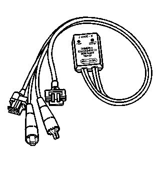
Tools Required
J 41450-B Universal CS Generator Test Harness
Test Description
Step | Action | Value(s) | Yes | No |
|---|---|---|---|---|
1 | Did you perform the Engine Electrical Diagnostic System Check? | -- | Go to Step 2 | |
2 | Start the engine, observe the charge indicator on the instrument panel cluster (IPC) . Does the charge indicator illuminate [or message center (DIC) display a charging system message]? | -- | Go to Step 3 | |
3 |
Important: The green POWER lamp of the tester should remain illuminated while the tester is being used.
Connect the red lead of the J 41450-B Universal CS Generator Test Harness to the generator output terminal. Does the green POWER lamp on the tester illuminate? | -- | Go to Step 6 | Go to Step 4 |
4 | Measure the voltage from the output terminal of the generator to the generator metal housing. Does the voltage measure equal to the specified value? | 12.0 V | Go to Step 14 | Go to Step 5 |
5 | Measure the voltage from the output terminal of the generator to the battery negative terminal. Does the voltage measure equal to the specified value? | 12.0 V | Go to Step 12 | Go to Step 11 |
6 |
Caution: Make sure that the load is completely turned off before connecting or disconnecting a carbon pile load tester to the battery. Otherwise, sparking could ignite battery gasses which are extremely flammable and may explode violently.
Important: Ensure that all generator output circuit wires pass through the inductive probe. Does the red DIAGNOSTIC lamp on the tester illuminate? | -- | Go to Step 7 | Go to Step 13 |
7 |
Does the red DIAGNOSTIC lamp on the tester illuminate? | -- | Go to Step 15 | Go to Step 8 |
8 |
Important: If the generator is not capable of producing the Load Test amps, operate the generator at it's maximum possible output. Does the red DIAGNOSTIC lamp on the tester illuminate? | -- | Go to Step 15 | Go to Step 9 |
9 |
Does the voltage measure greater than the specified value? | 0.5 V | Go to Step 11 | Go to Step 10 |
Does the voltage measure greater than the specified value? | 0.5 V | Go to Step 12 | Go to Step 16 | |
11 | Repair the high resistance or an open in the output circuit of the generator. Refer to Circuit Testing and Wiring Repairs in Wiring Systems. Did you complete the repair? | -- | Go to Step 16 | -- |
12 | Repair the high resistance or open in the ground circuit of the generator. Refer to Circuit Testing and Wiring Repairs in Wiring Systems. Did you complete the repair? | -- | Go to Step 16 | -- |
13 |
Does the red DIAGNOSTIC lamp illuminate? | -- | Go to Step 15 | Go to Step 14 |
14 | There is a problem with the J 41450-B . Refer to the manufacturers instructions, how to test the J 41450-B for proper operation. Has the J 41450-B tester been replaced? | -- | Go to Step 3 | -- |
15 | Replace the generator. Refer to Generator Replacement . Did you complete the replacement? | -- | Go to Step 16 | -- |
16 | Operate the vehicle in order to verify the repair. Did you correct the condition? | -- | System OK | Go to Step 2 |
