Tools Required
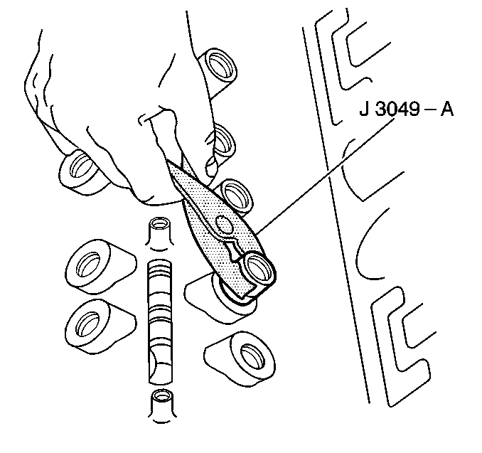
J 3049-A Valve Lifter Remover
Removal Procedure
- Remove the lower intake manifold. Refer to Lower Intake Manifold Replacement .
- Remove the valve rocker arms and the valve pushrods. Refer to Valve Rocker Arm and Push Rod Replacement .
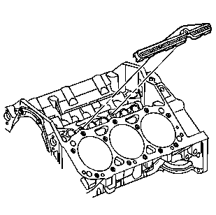
- Remove the bolts and valve lifter pushrod guide.
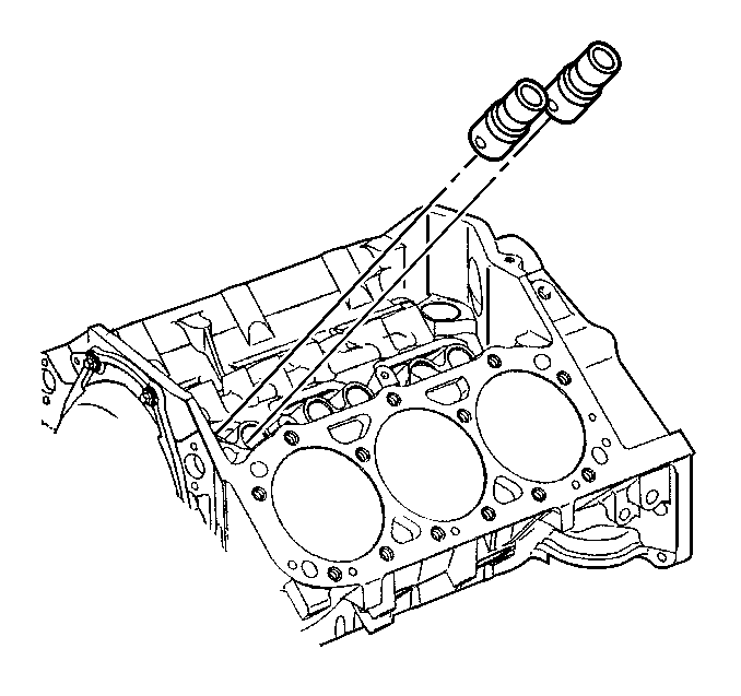
- Remove the valve lifters.
- Use the J 3049-A in order to remove the stuck valve lifters.
- Use a cleaning solvent and a shop towel to clean any varnish from the valve lifter bores.
- Inspect the valve lifter bores for excessive wear or scoring. Replace the engine block if there is excessive wear or deep scoring.
- Inspect the camshaft for wear or damage. If the wear is questionable remove the camshaft and inspect. Refer to Camshaft and Bearings Cleaning and Inspection in Engine Unit Repair.
- Clean and inspect the valve lifters and the valve pushrod guide. Refer to Valve Lifters and Guides Cleaning and Inspection in Engine Unit Repair.

Important: Place the components in a rack so that the components can be reinstalled to their original location.

Important: Place the valve lifters in the rack in the upright position in order to maintain the oil inside the valve lifters.

Important: Some valve lifters may be stuck in the valve lifter bores because of gum or varnish deposits and may require the use of for removal.
Installation Procedure
Important: It is normal for NEW lifters to make a slight ticking noise when the engine is first started. Increasing the engine RPMs slightly to raise oil pressure should stop the noise.
- Apply lubricant GM P/N 12345501 or equivalent to the valve lifter rollers.
- Install the valve lifters.
- Install the valve lifter pushrod guides.
- Install the valve rocker arms and pushrods. Refer to Valve Rocker Arm and Push Rod Replacement .
- Install the lower intake manifold. Refer to Lower Intake Manifold Replacement .

Important: If reusing the valve lifters, install the valve lifters in the original positions.

Notice: Use the correct fastener in the correct location. Replacement fasteners must be the correct part number for that application. Fasteners requiring replacement or fasteners requiring the use of thread locking compound or sealant are identified in the service procedure. Do not use paints, lubricants, or corrosion inhibitors on fasteners or fastener joint surfaces unless specified. These coatings affect fastener torque and joint clamping force and may damage the fastener. Use the correct tightening sequence and specifications when installing fasteners in order to avoid damage to parts and systems.
Tighten
Tighten the valve lifter pushrod guide bolts to 16 N·m
(12 lb ft).
