Exhaust Manifold Replacement - Right Side 4.3L
Removal Procedure
- Raise the vehicle. Refer to Lifting and Jacking the Vehicle in General Information.
- Remove the right front tire. Refer to Tire and Wheel Removal and Installation in Tires and Wheels.
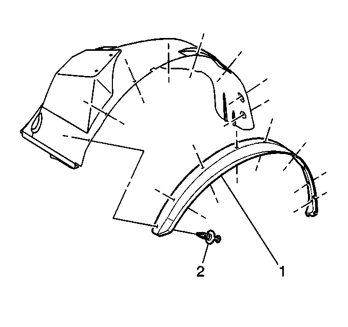
- Remove the right fender wheelhouse extension (1).
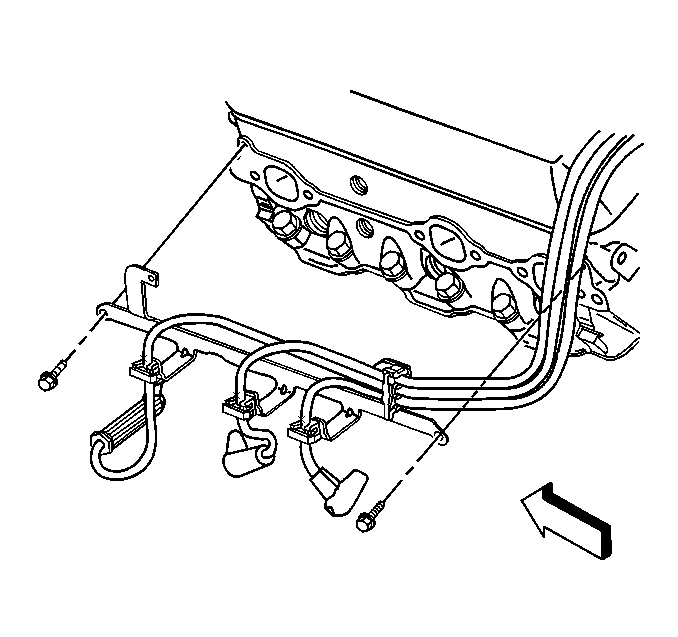
- Disconnect the spark plug wires from the spark plugs.
- Remove the bolts and the spark plug wire support.
- Remove the spark plugs.
- Remove the starter.
- Remove the catalytic converter assembly.
- Remove the AIR pipe from the exhaust manifold, if equipped.
- Remove the exhaust manifold bolts through the wheelhouse.
- Remove the exhaust manifold with the exhaust manifold gaskets and the spark plug wire shields from the engine.
- Clean all gasket surfaces.
Installation Procedure
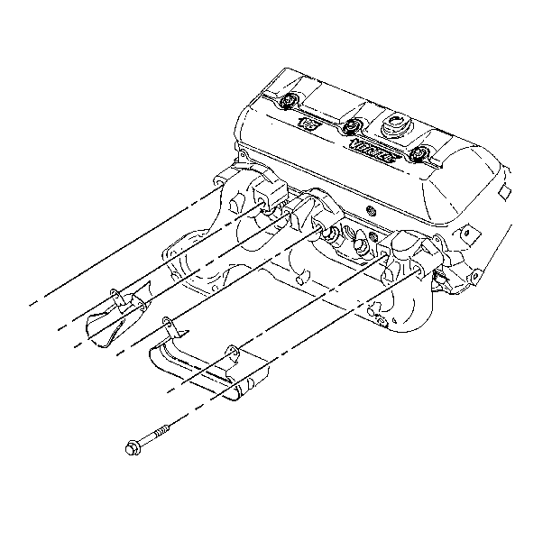
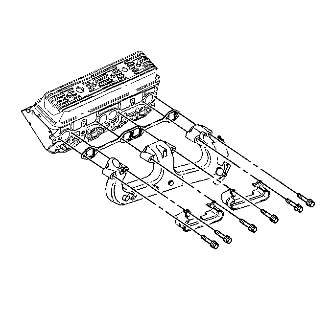
- Sub-assemble the NEW gaskets, the spark plug wire shields, and the bolts to the exhaust manifold.
- Ensure that the exhaust manifold bolts are held in place by the tabs on the exhaust manifold gaskets.
- Install the exhaust manifold. Refer to Exhaust Manifold Installation - Right Side .
- Install the AIR pipe to the exhaust manifold, if equipped. Refer to Secondary Air Injection Check Valve and Check Valve Pipe Replacement - Bank 1 in Engine Controls.
- Install the catalytic converter assembly. Refer to Catalytic Converter Replacement .
- Install the starter. Refer to Starter Motor Replacement in Engine Electrical.
- Install the spark plugs.
- Install the spark plug wire support and bolts.
- Install the spark plug wires. Refer to Spark Plug Replacement in Engine Controls -- 4.3L.
- Install the fender wheelhouse extension (1).
- Install the front tire. Refer to Tire and Wheel Removal and Installation in Tires and Wheels.
- Lower the vehicle.
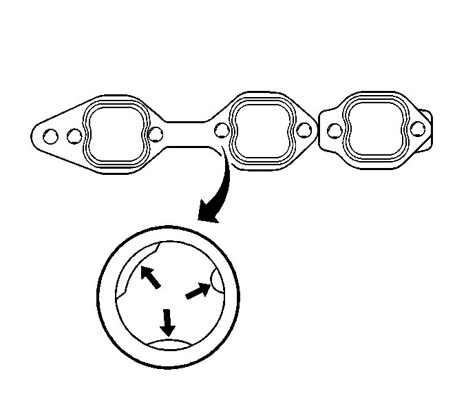
Important: To assist in installing the exhaust manifold to the engine, the tabs on a NEW exhaust manifold gasket will hold the gasket and the bolts in place.
Notice: Use the correct fastener in the correct location. Replacement fasteners must be the correct part number for that application. Fasteners requiring replacement or fasteners requiring the use of thread locking compound or sealant are identified in the service procedure. Do not use paints, lubricants, or corrosion inhibitors on fasteners or fastener joint surfaces unless specified. These coatings affect fastener torque and joint clamping force and may damage the fastener. Use the correct tightening sequence and specifications when installing fasteners in order to avoid damage to parts and systems.
Tighten
Tighten the spark plug wire support bolts to 12 N·m (106 lb in).
Exhaust Manifold Replacement - Right Side 5.7L
Removal Procedure
- Remove the exhaust pipe from the exhaust manifold.
- Remove the engine cover.
- Remove the air cleaner assembly.
- Remove the oil level indicator tube.
- Remove the exhaust manifold.
- Clean all sealing surfaces.
Installation Procedure
- Install the exhaust manifold.
- Install the oil level indicator tube.
- Install the exhaust pipe to the exhaust manifold.
- Install the air cleaner assembly.
- Install the engine cover.
Exhaust Manifold Replacement - Right Side 8.1L
Removal Procedure
- Remove the oil level indicator tube. Refer to Oil Level Indicator and Tube Replacement in Engine Mechanical 8.1L.
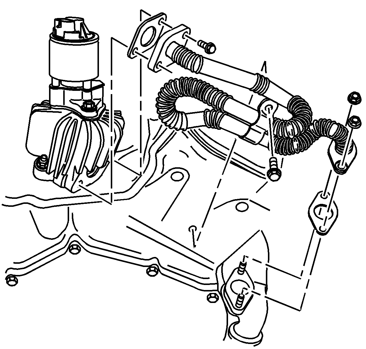
- If equipped, remove the secondary air injection (AIR) pipe nut from the fuel rail stud.
- If equipped, remove the AIR pipe bolts from the exhaust manifold.
- If equipped, disconnect the AIR pipe from the AIR pump pipe.
- If equipped, remove the AIR pipe.
- If equipped, remove the AIR pump pipe bolt from the cylinder head.
- If equipped, remove the AIR pump pipe.
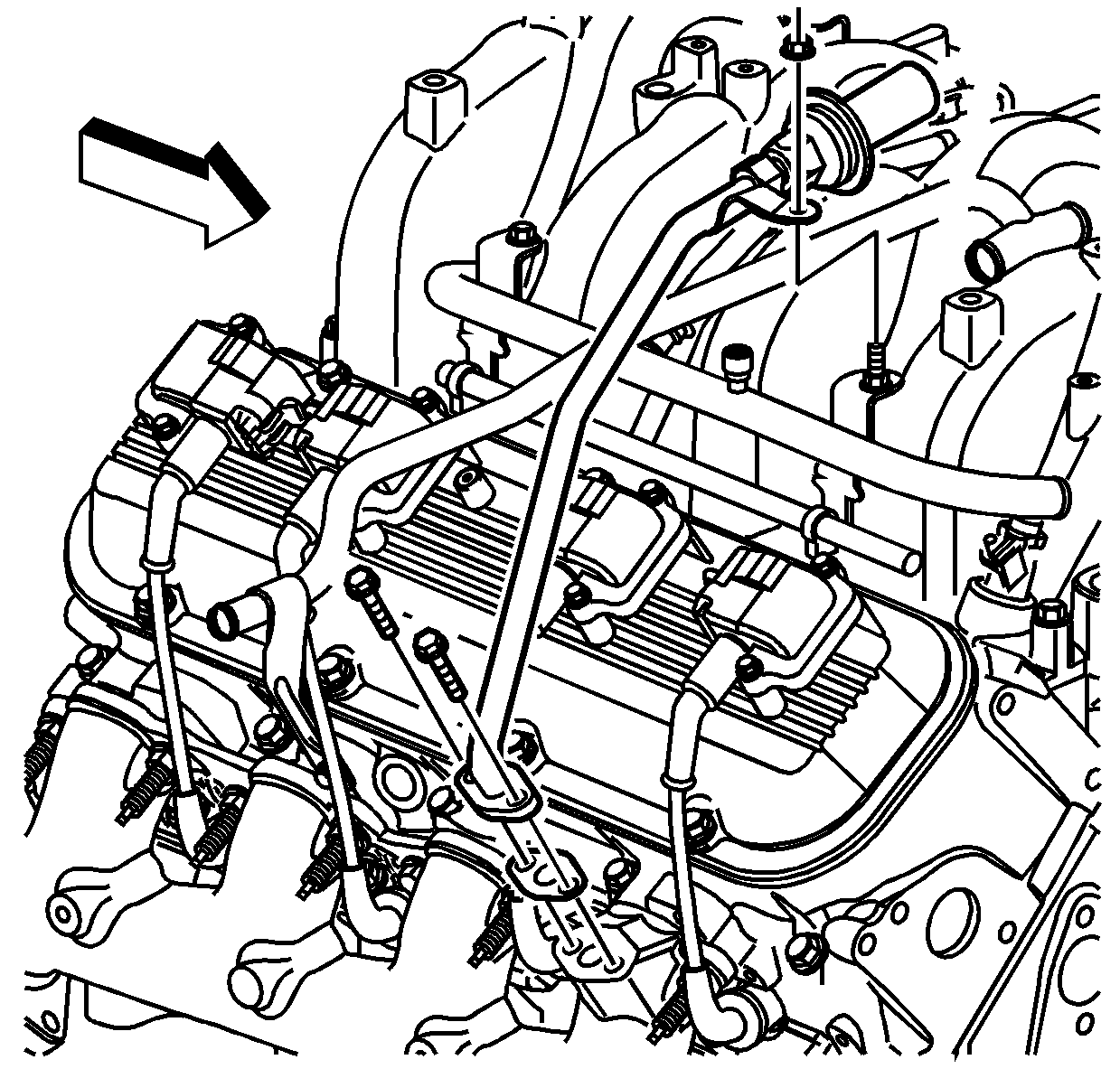
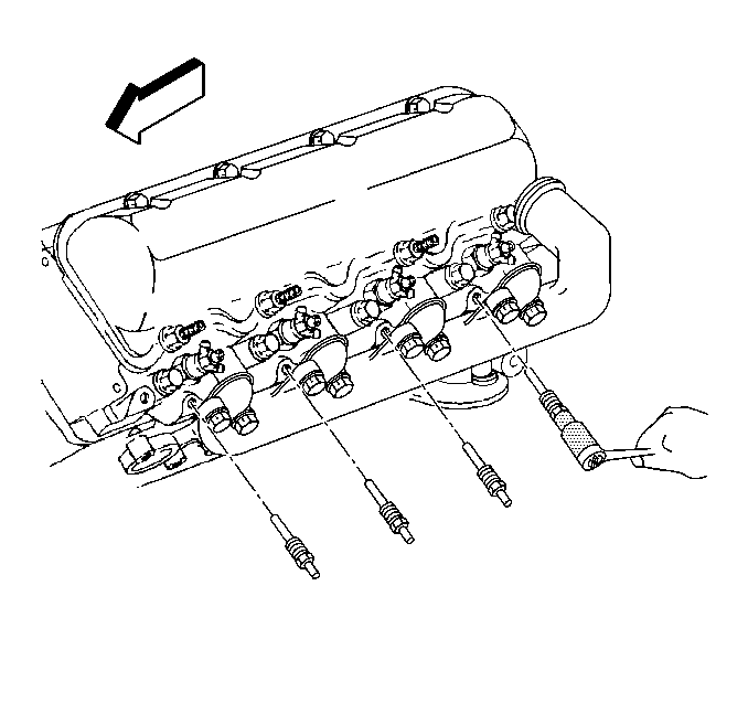
- Remove the spark plugs. Refer to Spark Plug Replacement in Engine Controls - 8.1L.
- Remove the EGR pipe nuts from the exhaust manifold.
- Remove and discard the EGR pipe gasket.
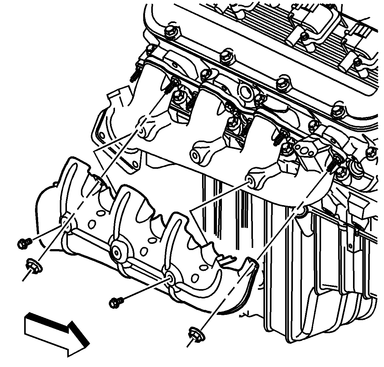
- Remove the exhaust manifold heat shield bolts and nuts.
- Reposition the exhaust manifold heat shield.
- Raise and suitably support the vehicle with safety stands. Refer to Lifting and Jacking the Vehicle in General Information.
- Remove the right catalytic converter. Refer to Catalytic Converter Replacement .
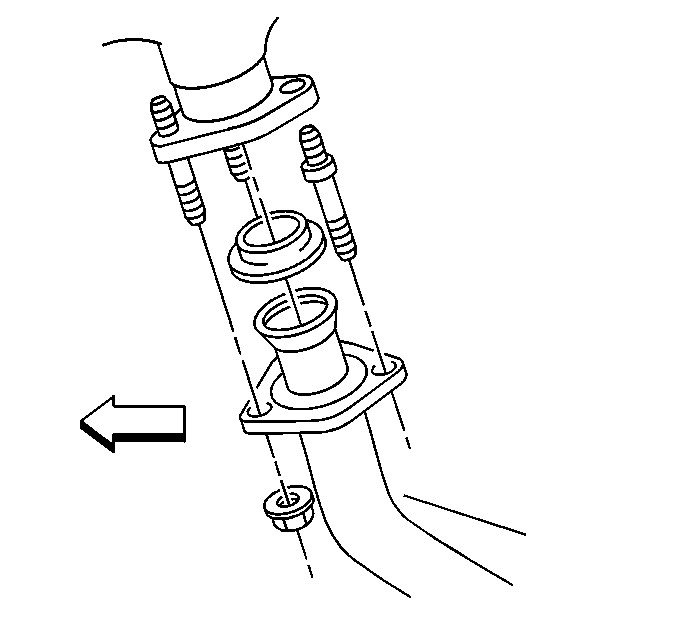
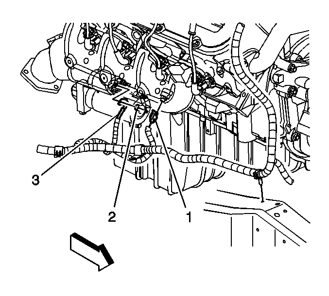
- Disconnect the knock sensor electrical connector (1).
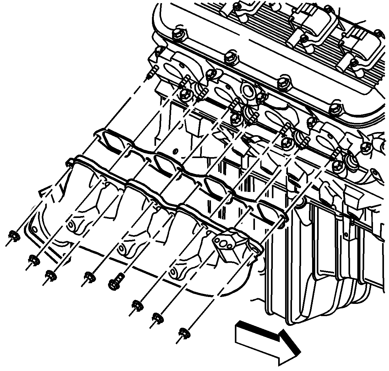
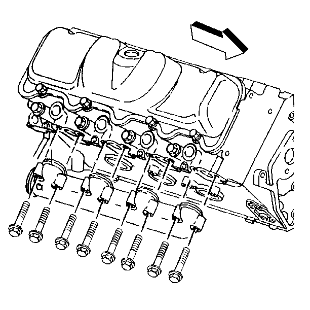
- Remove the exhaust manifold bolt and nuts.
- Remove the exhaust manifold and heat shield.
- Remove and discard the exhaust manifold gasket.
Installation Procedure
- Install a NEW exhaust manifold gasket.
- Install the exhaust manifold and heat shield.
- Install the exhaust manifold bolt and nuts.
- Connect the knock sensor electrical connector (1).
- Install the right catalytic converter. Refer to Catalytic Converter Replacement .
- Lower the vehicle.
- Position the exhaust manifold heat shield.
- Install the exhaust manifold heat shield bolts and nuts.
- Install a NEW EGR pipe gasket.
- Install the EGR pipe nuts to the exhaust manifold until snug.
- Install the spark plugs. Refer to Spark Plug Replacement in Engine Controls - 8.1L.
- If equipped, install the AIR pump pipe.
- If equipped, install the AIR pump pipe bolt to the cylinder head.
- If equipped, install the AIR pipe.
- If equipped, connect the AIR pipe to the AIR pump pipe.
- If equipped, install the AIR pipe bolts to the exhaust manifold.
- If equipped, Install the AIR pipe nut to the fuel rail stud.
- Install the oil level indicator tube. Refer to Oil Level Indicator and Tube Replacement in Engine Mechanical 8.1L.
Notice: Use the correct fastener in the correct location. Replacement fasteners must be the correct part number for that application. Fasteners requiring replacement or fasteners requiring the use of thread locking compound or sealant are identified in the service procedure. Do not use paints, lubricants, or corrosion inhibitors on fasteners or fastener joint surfaces unless specified. These coatings affect fastener torque and joint clamping force and may damage the fastener. Use the correct tightening sequence and specifications when installing fasteners in order to avoid damage to parts and systems.
Tighten
| • | Tighten the exhaust manifold bolt to 35 N·m (26 lb ft). |
| • | Tighten the exhaust manifold nuts to 16 N·m (12 lb ft). |
Tighten
Tighten the exhaust manifold heat shield bolts and nuts to 25 N·m
(18 lb ft).
Tighten
Tighten the EGR pipe nuts to the exhaust manifold to 30 N·m
(22 lb ft).
Tighten
Tighten the AIR pump pipe bolt to 50 N·m (37 lb ft).
Tighten
Tighten the AIR pipe bolts to 25 N·m (18 lb ft).
Tighten
Tighten the AIR pipe nut to 12 N·m (106 lb in).
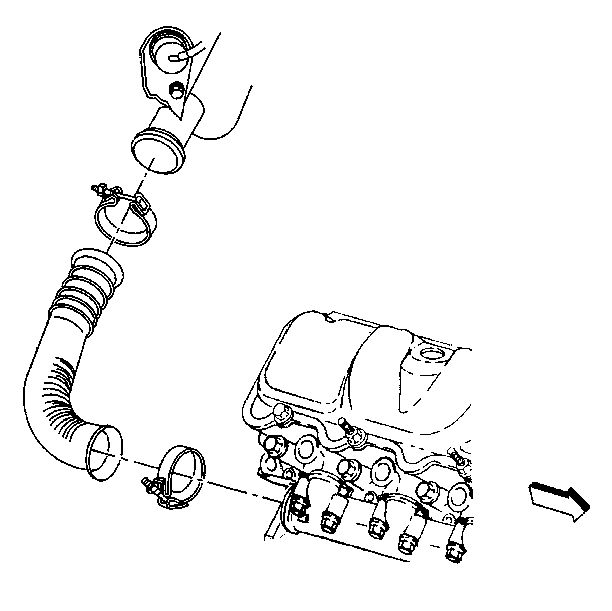
Exhaust Manifold Replacement - Right Side 6.5L
Removal Procedure
- Remove the engine cover from the vehicle. Refer to Engine Cover Replacement in Interior Trim.
- Raise the vehicle enough to remove the right front wheel to gain access to the glow plugs.
- Remove the splash shields from the frame to the wheel housing. Refer to Wheelhouse Splash Shield Replacement in Body Front End.
- Remove the right exhaust pipe clamp from the exhaust pipe to the turbocharger.
- Remove the right exhaust pipe clamp from the exhaust pipe to the exhaust manifold.
- Remove the right exhaust pipe.
- Remove the glow plugs from the cylinder head.
- Raise the vehicle and support with safety stands. Refer to Lifting and Jacking the Vehicle in General Information.
- Remove the exhaust manifolds bolts from the cylinder head.
- Remove the exhaust manifold from the cylinder head.
- Inspect and clean the sealing surfaces on the cylinder head and the exhaust manifold.
Important: To remove the glow plugs from number 2 and 4 cylinders, you may have to remove them through the wheel well.
Installation Procedure
- Install the exhaust manifold to the cylinder head.
- Install the exhaust manifold bolts.
- Install the exhaust pipe from the turbocharger to the exhaust manifold.
- Slide the exhaust clamps over the exhaust manifold and turbocharger.
- Place the clamps in the correct position as shown.
- Tighten the clamps at the exhaust manifold.
- Install the glow plugs in the cylinder head.
- Install the splash shields from the frame to the wheel housing. Refer to Wheelhouse Splash Shield Replacement in Body Front End.
- Install the right front wheel (if removed).
- Lower the vehicle.
- Install the engine cover in the vehicle. Refer to Engine Cover Replacement in Interior Trim.
Notice: Use the correct fastener in the correct location. Replacement fasteners must be the correct part number for that application. Fasteners requiring replacement or fasteners requiring the use of thread locking compound or sealant are identified in the service procedure. Do not use paints, lubricants, or corrosion inhibitors on fasteners or fastener joint surfaces unless specified. These coatings affect fastener torque and joint clamping force and may damage the fastener. Use the correct tightening sequence and specifications when installing fasteners in order to avoid damage to parts and systems.
Tighten
Tighten the exhaust manifold bolts to 35 N·m (26 lb ft).
Important: In order to ensure heat shield clearance, locate the exhaust pipe clamps as shown.
Tighten
Tighten the clamps to 10 N·m (90 lb in).
