Circuit Description
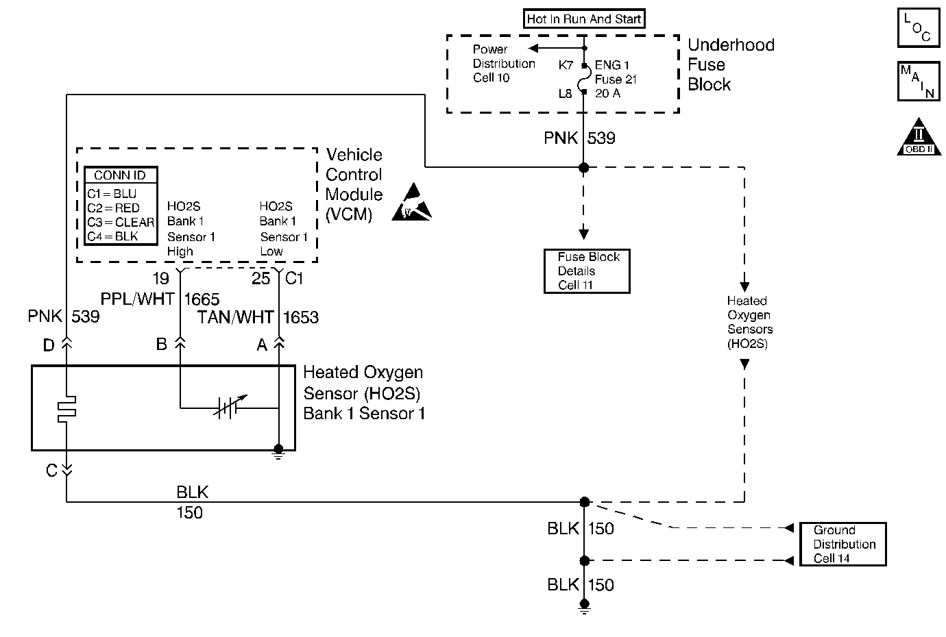
The heated oxygen sensor (HO2S) is a sensor designed to create a voltage relative to the oxygen content in the engine exhaust stream. The control module supplies the HO2S with signal high and low circuits. Ignition voltage and ground are supplied to the HO2S heater by independent circuits. The oxygen content of the exhaust indicates when the engine is operating lean or rich. When the HO2S detects that the engine is operating rich, the signal voltage is high, and decreases the signal voltage as the engine runs leaner. This oscillation above and below the bias voltage, sometimes referred to as activity or switching, can be monitored with the HO2S signal voltage.
The HO2S contains a heater that is necessary in order to quickly warm the sensor to operating temperature. The heater also maintains the operating temperature during extended idle conditions. The HO2S needs to be at a high temperature in order to produce a voltage. When the HO2S reaches operating temperature, the control module monitors the HO2S bias, or reference, voltage. It also monitors the HO2S signal voltage for Closed Loop fuel control. During normal Closed Loop fuel control operation, the control module will add fuel, or enrich the mixture, when the HO2S detects a lean exhaust content. The control module will subtract fuel, or "lean-out" the mixture, when the HO2S detects a rich exhaust condition.
Certain vehicle models utilize an oxygen sensor behind the catalytic converter in order to monitor catalyst efficiency.
This diagnostic trouble code (DTC) determines if the HO2S is functioning properly. It checks for an adequate number of HO2S voltage transitions above and below the bias range of 300-600 mV. This DTC sets when the vehicle control module (VCM) fails to detect a minimum number of voltage transitions above and below the bias range during the test period. Possible causes of this DTC are:
| • | An open or a short to voltage on either the HO2S signal or HO2S low circuits |
| • | A malfunctioning HO2S |
| • | A problem in the HO2S heater or its circuit |
| • | A faulty HO2S ground |
This DTC is designed to detect an HO2S voltage that remains at a low (lean) voltage for more than a specified number of seconds during the test conditions. This DTC is set under the following conditions:
| • | There is an HO2S circuit fault that results in a false lean exhaust condition. |
| • | The HO2S is correctly detecting a lean air/fuel ratio resulting from either a vacuum leak or a fuel control system fault. |
Conditions for Running the DTC
| • | No active TP sensor DTCs |
| • | No active EVAP DTCs |
| • | No active IAT sensor DTCs |
| • | No active MAP sensor DTCs |
| • | No active ECT sensor DTCs |
| • | No active MAF sensor DTCs |
| • | No active misfire DTCs |
| • | No intrusive test in progress |
| • | No device controls active |
| • | The system voltage is between 11.7-18 volts |
Lean Test Enable
| • | The system is in closed loop |
| • | The air/fuel ratio is between 14.5-14.8 |
| • | The throttle position is between 3.5-99 percent |
| • | The above conditions are met for 5 seconds |
Power Enrichment Lean Test Enable
| • | The system is in closed loop |
| • | Power enrichment mode is active |
| • | High speed fuel cut-off not active |
| • | The elapsed time since test enabled is more than 1 second |
Conditions for Setting the DTC
Lean Test
The O2 sensor voltage remains less than 86 mV for more than 50 seconds.
Power Enrichment Lean Test
The O2 sensor voltage remains less than 598 mV for more than 30 seconds
Action Taken When the DTC Sets
| • | The control module illuminates the malfunction indicator lamp (MIL) if a failure is detected during 2 consecutive key cycles. |
| • | The control module sets the DTC and records the operating conditions at the time the diagnostic failed. The failure information is stored in the scan tool Freeze Frame/Failure Records. |
Conditions for Clearing the MIL or DTC
| • | The control module turns OFF the MIL after 3 consecutive drive trips when the test has run and passed. |
| • | A history DTC will clear if no fault conditions have been detected for 40 warm-up cycles. A warm-up cycle occurs when the coolant temperature has risen 22°C (40°F) from the startup coolant temperature and the engine coolant reaches a temperature that is more than 70°C (158°F) during the same ignition cycle. |
| • | Use a scan tool in order to clear the DTCs. |
Diagnostic Aids
Important: Never solder the HO2S wires. For proper wire and connection repair refer to Wiring Repairs or Connector Repairs in Wiring Systems.
Using the scan tool, observe the LT fuel trim values at the different RPM and the air flow conditions. The scan tool also displays the fuel trim cells, so the LT fuel trim values can be checked in each of the cells in order to determine when the DTC may have set. If the conditions for this DTC exist, the LT fuel trim values measure around 158 or greater.
Check for the following conditions:
| • | A sensor pigtail may be mispositioned and contacting the exhaust system. |
| • | An intermittent short to ground in the signal circuit between the VCM connector and HO2S. |
| • | A poor VCM to the engine block ground. |
| • | Lean injectors: Perform the Injector Balance Test. Refer to Fuel Injector Balance Test with Tech 2 . |
| • | Fuel Contamination: Water, even in small amounts, near the in-tank fuel pump inlet can be delivered to the injectors. The water causes a lean exhaust and can also set this DTC. Refer to Alcohol/Contaminants-in-Fuel Diagnosis . |
| • | Fuel pressure: If the pressure is too low, the system will be lean. In order to confirm, monitor a fuel pressure while driving the vehicle at various speeds and loads. Refer to Fuel System Diagnosis . |
| • | Exhaust leaks: If there is an exhaust leak, the engine may pull the outside air into the exhaust. and past the sensor. Refer to Exhaust System Inspection in Engine Exhaust. |
| • | Vacuum or the Crankcase leaks can cause a lean condition or a possibly a high idle. |
An intermittent may be caused by any of the following conditions:
| • | A poor connection |
| • | Rubbed through wire insulation |
| • | A broken wire inside the insulation |
Thoroughly check any circuitry that is suspected of causing the intermittent complaint. Refer to Intermittents and Poor Connections Diagnosis in Wiring Systems.
If a repair is necessary, refer to Wiring Repairs or Connector Repairs in Wiring Systems.
Test Description
The numbers below refer to the step numbers on the diagnostic table.
Step | Action | Value(s) | Yes | No | ||||||||||||
|---|---|---|---|---|---|---|---|---|---|---|---|---|---|---|---|---|
1 |
Important: Before clearing the DTCs, record Freeze Frame and the Failure Records for reference. The control module's data is deleted once the Clear Info function is used. Did you perform the Powertrain On-Board Diagnostic (OBD) System Check? | -- | ||||||||||||||
2 |
Is the HO2S voltage fixed less than the value specified? | 86 mv | ||||||||||||||
3 | This DTC is intermittent. Are any additional DTCs stored? | -- | Go to the applicable DTC table | Go to Diagnostic Aids | ||||||||||||
4 |
Is the HO2S voltage within the specified value range? | 351-551 mV | ||||||||||||||
Did you find a problem? | -- | |||||||||||||||
6 |
Is the resistance at the specified value on both tests? | ∞ | ||||||||||||||
7 | Repair the HO2S signal HIGH circuit shorted to ground or shorted to the HO2S LOW circuit. Refer to Wiring Repairs in Wiring Systems. Is the action complete? | -- | -- | |||||||||||||
8 | Replace the HO2S. Refer to Heated Oxygen Sensor Replacement . Is the action complete? | -- | -- | |||||||||||||
9 |
Is the action complete? | -- | -- | |||||||||||||
10 |
Does the scan tool indicate that this diagnostic ran and passed? | -- | ||||||||||||||
11 | Does the scan tool display any additional undiagnosed DTCs? | -- | Go to the applicable DTC table | System OK |
