Circuit Description
The EBCM microprocessor will ground the indicated solenoid coil (RF dump/isolation, LF dump/isolation, or Rear dump/isolation) circuit to energize the solenoid coil whenever the solenoid valve is needed. Refer to ABS Braking Mode in ABS Operation . The magnetic force created by the solenoid coil will close the isolation valve.
Conditions for Setting the DTC
Open Circuit
| • | The ABS bulb check is complete |
| • | Low voltage exists on the EBCM solenoid driver circuit when high voltage is expected (the solenoid is not energized) |
Shorted Circuit
| • | The ABS bulb check is complete |
| • | High voltage is present on the EBCM solenoid driver circuit when the voltage is expected to be low (solenoid energized). |
Action Taken When the DTC Sets
| • | The ABS indicator lamp turns on |
| • | The ABS disables |
DTCs C0241-C0258 are Ignition Latched DTCs, which indicates the above actions remain true until the ignition is turned to OFF (even if the cause of the DTC is intermittent).
Conditions for Clearing the DTC
| • | Repair the conditions responsible for setting the DTC |
| • | Use the Scan Tool Clear DTCs function |
Diagnostic Aids
This DTC usually sets because of an open/shorted solenoid coil, the solenoid coil is located within the EBCM and is not serviceable. If the test does not repair the DTC, then replace the EBCM.
If this DTC sets with other DTCs, check for the following conditions:
| • | A poor EBCM power or signal ground |
| • | A poor EBCM power or ignition feed |
Test Description
The numbers below refer to the steps in the diagnostic table:
-
This step determines the resistance of the power ground circuit.
-
This step determines the battery voltage available to the EBCM.
-
This step determines the resistance of the signal ground circuit.
-
This step determines the ignition voltage available to the EBCM.
Step | Action | Value(s) | Yes | No |
|---|---|---|---|---|
1 | Was the Diagnostic System Check performed? | -- | Go to Step 2 | |
2 |
Is the connector in good condition? | -- | Go to Step 3 | Go to Step 11 |
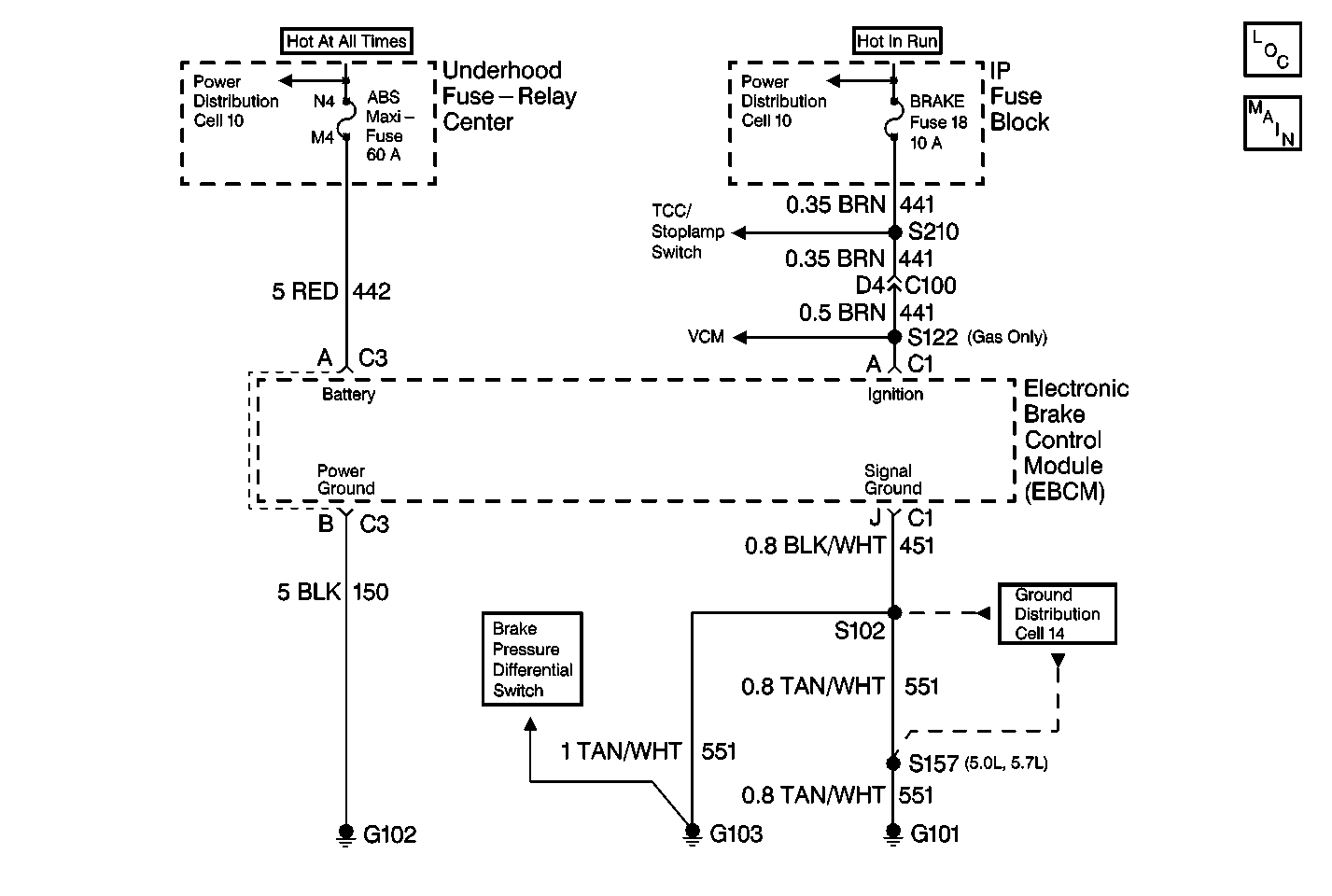
Measure the resistance between terminal B of the 2-way EBCM harness connector and the ground using a J 39200 . Is the resistance measurement within the specified range? | 0.1-0.5 ohms | Go to Step 4 | Go to Step 12 | |
Measure the voltage between terminal A of the 2-way EBCM harness connector and the ground using a J 39200 . Is the voltage equal to or greater than the specified value? | 10.0 V | Go to Step 6 | Go to Step 5 | |
5 | Inspect the 60A ABS fuse. Is the 60A ABS fuse open? | -- | Go to Step 13 | Go to Step 14 |
6 |
Is the connector in good condition? | -- | Go to Step 7 | Go to Step 15 |
Using a J 39200 , measure the resistance between terminal J of the 10-way EBCM harness connector and the ground. Is the resistance measurement within the specified range? | 0-2 ohms | Go to Step 8 | Go to Step 16 | |
Is the voltage equal to or greater than the specified value? | 10.0 V | Go to Step 10 | Go to Step 9 | |
9 | Inspect the 10-amp BRAKE fuse. Is the fuse open? | -- | Go to Step 17 | Go to Step 18 |
10 |
Does the DTC set as a current DTC? | -- | Go to Step 19 | Go to Diagnostic Aids |
11 | Repair the 2-way EBCM harness connector. Refer to Connector Repairs . Is the repair complete? | -- | -- | |
12 | Repair the open or the high resistance in the CKT 150. Refer to Wiring Repairs . Is the repair complete? | -- | -- | |
13 | Repair the short to ground in the CKT 442. Refer to Wiring Repairs . Is the repair complete? | -- | -- | |
14 | Repair the open or the high resistance in the CKT 442. Refer to Wiring Repairs . Is the repair complete? | -- | -- | |
15 | Repair the 10-way EBCM harness connector. Refer to Connector Repairs . Is the repair complete? | -- | -- | |
16 | Repair the open or the high resistance in the CKT 451. Refer to Wiring Repairs . Is the repair complete? | -- | -- | |
17 | Repair the short to ground in the CKT 441. Refer to Wiring Repairs . Is the repair complete? | -- | -- | |
18 | Repair the open or the high resistance in the CKT 441. Refer to Wiring Repairs . Is the repair complete? | -- | -- | |
19 | Replace the EBCM. Refer to Electronic Brake Control Module Replacement . Is the repair complete? | -- | -- |
