DTC P0719 Brake Switch Circuit Low Input Diesel
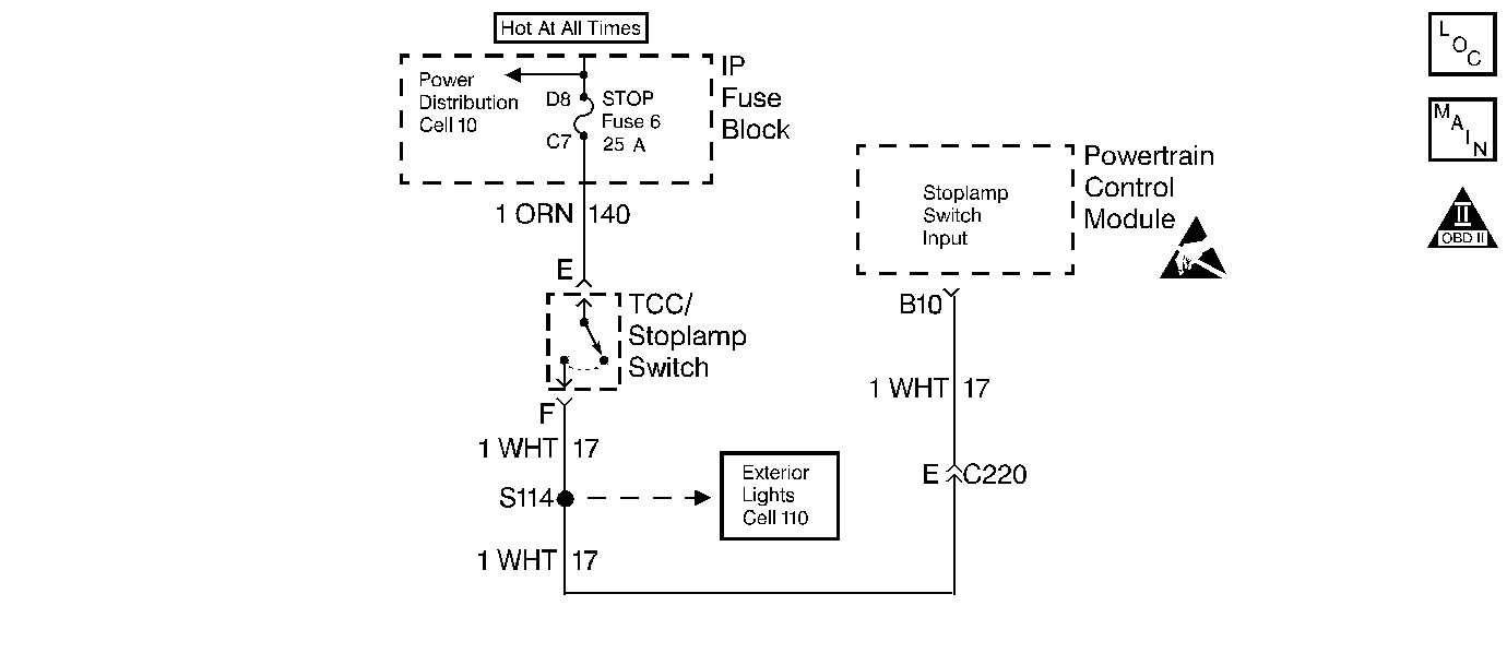
Circuit Description
The normally open TCC stoplamp switch indicates brake pedal status to the Powertrain Control Module (PCM). Applying the brake pedal closes the switch, supplying voltage to the PCM. Releasing the brake pedal interrupts voltage to the PCM.
If the PCM detects an open brake switch (stuck OFF) during decelerations, then DTC P0719 sets. DTC P0719 is a type D DTC.
Conditions for Setting the DTC
| • | No OSS Sensor DTC P0722 or P0723. |
| • | The PCM detects an open TCC stoplamp switch/circuit (0 volts) and the following sequence of events occurs ten consecutive times: |
| 1. | The vehicle speed is greater than 32 km/h (20 mph) for 6 seconds. |
| 2. | Then the vehicle speed is 8-32 km/h (5-20 mph) for 3 seconds. |
| 3. | Then the vehicle speed is less than 8 km/h (5 mph). |
| 4. | DTC P0719 has not passed. |
Action Taken When the DTC Sets
| • | The PCM does not illuminate the Malfunction Indicator Lamp (MIL). |
| • | For TCC scheduling, the PCM disregards the brake switch state if the TP Sensor is greater than 12% and the vehicle speed is greater than 20 mph. |
Conditions for Clearing the DTC
- A scan tool can clear the DTC from the PCM history. The PCM clears the DTC from the PCM history if the vehicle completes 40 warm-up cycles without a failure reported.
- The PCM cancels the DTC default actions when the fault no longer exists and the ignition is OFF long enough in order to power down the PCM
Diagnostic Aids
| • | Inspect the wiring for poor electrical connections at the PCM. Inspect the wiring for poor electrical connections at the TCC brake switch. Look for the following problems: |
| - | A bent terminal |
| - | A backed out terminal |
| - | A damaged terminal |
| - | Poor terminal tension |
| - | A chafed wire |
| - | A broken wire inside the insulation |
| • | When diagnosing for an intermittent short or open, massage the wiring harness while watching the test equipment for a change. |
| • | Ask about the customer's driving habits and any unusual driving conditions he or she might have, such as stop and go traffic or expressway driving. |
| • | Inspect the break switch for proper mounting and adjustment. |
| • | First diagnose and clear any engine DTCs codes that are present. Then inspect for any transmission DTCs that may have reset. |
Test Description
The numbers below refer to the step numbers on the diagnostic table.
-
This step isolates the brake switch as a source for setting the DTC.
-
This step tests for a short to ground between the fuse and the TCC Stop Light Switch.
-
This step tests for a short to ground in circuit 17.
-
This step removes the PCM from circuit 17 as the source of a short to ground.
Step | Action | Value(s) | Yes | No | ||||||
|---|---|---|---|---|---|---|---|---|---|---|
1 | Was the Powertrain On-Board Diagnostic (OBD) System Check performed? | -- | ||||||||
2 |
Important: Before clearing the DTCs, use the scan tool in order to record the Freeze Frame and Failure Records for reference. The Clear Info function will erase the data. Is the test lamp ON? | -- | ||||||||
Install a J 36169-A Fused Jumper Wire between terminals E (ORN) and F (circuit 17 WHT) of the TCC brake switch connector. Did the TCC Brake Switch status change from Open to Closed? | -- | |||||||||
4 |
Refer to Electrical Diagnosis, Section 8. Is the fuse open? | -- | ||||||||
Replace the brake fuse. Does the replacement fuse open immediately? | -- | |||||||||
6 | Inspect circuit 140 for a short to ground. Refer to Electrical Diagnosis, Section 8. Did you find and repair the problem? | -- | -- | |||||||
Does the fuse open immediately? | -- | Intermittent short to ground. Go to Diagnostic Aids. | ||||||||
Does the fuse open immediately? | -- | |||||||||
9 | Inspect circuit 17 for a short to ground. Refer to Electrical Diagnosis, Section 8. Did you find and repair the problem? | -- | -- | |||||||
10 | Replace the brake switch. Refer to Brake Switch Replacement, Section 5. Is the replacement complete? | -- | -- | |||||||
11 | Inspect circuit 140 for an open. Refer to Electrical Diagnosis, Section 8. Did you find and correct a problem? | -- | -- | |||||||
12 | Inspect circuit 17 for an open. Refer to Electrical Diagnosis, Section 8. Did you find a problem? | -- | ||||||||
13 | Inspect the following components for corrosion or shorting together.
Did you find a problem? | -- | ||||||||
14 | Replace the PCM. Refer to Powertrain Control Module Replacement/Programming , Section 6. Is the replacement complete? | -- | -- | |||||||
15 | In order to verify your repair, perform the following procedure:
Has the test run and passed? | -- | System OK |
DTC P0719 Brake Switch Circuit Low Input Gas
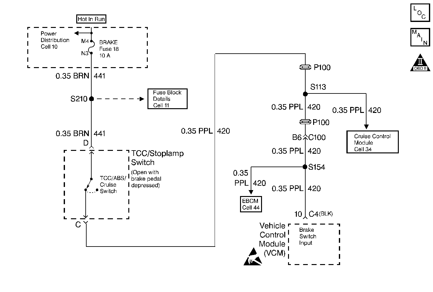
Circuit Description
The brake switch indicates the brake pedal status. The normally-closed brake switch supplies a B+ signal on circuit 420 to the Vehicle Control Module (VCM). The signal voltage circuit opens when the brakes are applied. The VCM uses the open signal voltage circuit in order to de-energize the Torque Converter Clutch Pulse Width Modulation Solenoid Valve (TCC PWM Sol. Valve) when the brakes are applied.
If the VCM detects an open brake switch during accelerations, then DTC P0719 sets. DTC P0719 is a type D DTC. For California emissions vehicles, DTC P0719 is a type B DTC.
Conditions for Setting the DTC
- No OSS DTC P0502.
- The VCM detects an open brake switch/circuit (0 volts) for 15 minutes without going closed for 2 seconds.
- The following sequence of events occurs seven consecutive times:
- DTC P0719 has not passed.
| • | The vehicle speed is less than 8 km/h (5 mph). |
| • | Then the vehicle speed is 8-32 km/h (5-20 mph) for 3.5 seconds. |
| • | Then the vehicle speed is greater than 32 km/h (20 mph) for 6 seconds. |
Action Taken When the DTC Sets
| • | The VCM inhibits fourth gear. |
| • | The VCM freezes shift adapts. |
| • | The VCM illuminates the Malfunction Indicator Lamp (MIL) on California emissions vehicles. |
Conditions for Clearing the DTC
- For California Emissions vehicles, the VCM turns OFF the MIL after three consecutive ignition cycles without a failure reported.
- A scan tool can clear the DTC from the VCM history. The VCM clears the DTC from the VCM history if the vehicle completes 40 warm-up cycles without a failure reported.
- The VCM cancels the DTC default actions when the fault no longer exists and the ignition is OFF long enough in order to power down the VCM.
Diagnostic Aids
| • | Inspect the wiring for poor electrical connections at the VCM. Inspect the wiring for poor electrical connections at the TCC brake switch. Look for the following problems: |
| - | A bent terminal |
| - | A backed out terminal |
| - | A damaged terminal |
| - | Poor terminal tension |
| - | A chafed wire |
| - | A broken wire inside the insulation |
| • | When diagnosing for an intermittent short or open, massage the wiring harness while watching the test equipment for a change. |
| • | Ask about the customer's driving habits and any unusual driving conditions he or she might have, such as stop and go traffic or expressway driving. |
| • | Inspect the brake switch for proper mounting and adjustment. |
| • | Inspect for the most current calibration ID and the latest bulletins. |
| • | First diagnose and clear any engine DTCs or TP Sensor codes that are present. Then inspect for any transmission DTCs that may have reset. |
Test Description
The numbers below refer to the step numbers on the diagnostic table.
Step | Action | Value(s) | Yes | No | ||||||
|---|---|---|---|---|---|---|---|---|---|---|
1 | Was the Powertrain On-Board Diagnostic (OBD) System Check performed? | -- | Go to: Powertrain On Board Diagnostic (OBD) System Check (4.3L) Powertrain On Board Diagnostic (OBD) System Check (5.7L and 7.4L) | |||||||
2 |
Important: Before clearing the DTCs, use the scan tool in order to record the Freeze Frame and Failure Records for reference. The Clear Info function will erase the data. Is the test lamp ON? | -- | ||||||||
Install a J 36169-A Fused Jumper Wire between terminals C and D of the brake switch connector. Did the TCC Brake Switch status change from Open to Closed? | -- | |||||||||
4 |
Refer to Electrical Diagnosis, Section 8. Is the fuse open? | -- | ||||||||
5 | Inspect circuit 441 for a short to ground. Refer to Electrical Diagnosis, Section 8. Did you find a problem? | -- | ||||||||
6 | Inspect circuit 420 for a short to ground. Refer to Electrical Diagnosis, Section 8. Did you find a problem? | -- | ||||||||
7 | Replace the brake switch. Refer to Brake Switch Replacement, Section 5. Is the replacement complete? | -- | -- | |||||||
8 | Inspect circuit 441 for an open. Refer to Electrical Diagnosis, Section 8. Did you find and correct a problem? | -- | -- | |||||||
9 | Inspect circuit 420 for an open. Refer to Electrical Diagnosis, Section 8. Did you find a problem? | -- | ||||||||
10 | Replace the VCM. Refer to VCM Replacement/Programming (With KS Calibration PROM) , Section 6. Is the replacement complete? | -- | -- | |||||||
11 | In order to verify your repair, perform the following procedure:
Has the test run and passed? | -- | System OK |
