Circuit Description
Canister purge is controlled by a solenoid valve that allows ported vacuum to purge the canister when energized. The Vehicle Control Module (VCM) supplies a ground to energize the solenoid valve (purge ON). The purge solenoid control by the VCM is Pulse Width Modulated (PWM) or turned ON and OFF several times a second. The duty cycle (pulse width) is determined by Closed Loop feed back from the Heated Oxygen Sensor (HO2S). The duty cycle is calculated by the VCM and the output is commanded when certain conditions have been met.
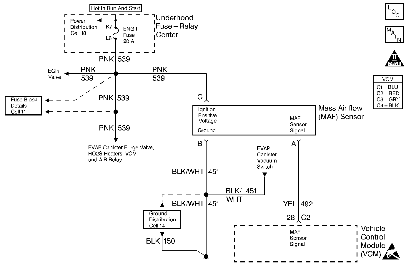
A vacuum switch in the purge line is used to detect when the system is being purged. The normally closed switch will open when less than 1 in. Hg is present in the purge line. The VCM supplies a 12 V reference to the switch to ensure the evaporative emission control system is working properly. If the switch is closed (no EVAP vacuum) when the VCM is commanding purge, a DTC will be set. DTC P0441 is a type B DTC.
Conditions for Setting the DTC
| • | Purge solenoid diagnostic vacuum switch DTC not set. |
| • | No IAC DTCs. |
| • | No MAP DTCs. |
| • | No TP sensor DTCs. |
| • | No EGR DTCs. |
| • | BARO greater than 75 kPa. |
| • | ECT less than 110°C. |
| • | Powerup IAT greater than -18°C. |
| • | IAT less than or equal to 90°C. |
| • | The change in ECT/IAT less than or equal to 90°C. |
| • | Purge DC greater than or equal to 90%. |
| • | MAP greater than or equal to 20 kPa but less than or equal to 80 kPa. |
| • | Throttle position greater than or equal to 5% but less than or equal to 60%. |
| • | Engine speed greater than or equal to 800 RPM but less than or equal to 3000 RPM. |
Action Taken When the DTC Sets
The VCM will turn ON the malfunction indicator lamp (MIL) after two consecutive test cycles with the fault active.
Conditions for Clearing the MIL/DTC
The VCM turns OFF the MIL after 3 consecutive driving trips without a fault condition present. A history DTC will clear if no fault conditions have been detected for 40 warm-up cycles (the coolant temperature has risen 22°C (40°F) from the start-up coolant temperature and the engine coolant temperature exceeds 71°C (160°F) during that same ignition cycle) or the scan tool clearing feature has been used.
Diagnostic Aids
Make a visual check of vacuum hose(s). Check throttle body for possible cracked, broken, or plugged vacuum block. Check engine for possible mechanical problem.
Test Description
Number(s) below refer to the step numbers on the Diagnostic Table.
-
The solenoid valve will click when commanded ON and OFF by the scan tool. This determines if the VCM can control the solenoid valve.
-
Ported (off idle) vacuum is used at the solenoid valve. Vacuum will only be seen off idle with a vacuum gauge.
-
Disconnecting the vacuum switch electrical connector opens the 5 V reference circuit from the VCM which indicates that purge is present. Leaving the switch disconnected will cause a DTC P1441.
-
If voltage is not available to the solenoid valve, the VCM will not be able to command the solenoid valve ON or OFF.
-
Determines if the solenoid valve couldn't be commanded due to an electrical circuit problem or faulty solenoid.
Step | Action | Value(s) | Yes | No |
1 |
Important: Before clearing DTC(s) use the scan tool to record freeze frame and failure records for reference, as data will be lost when Clear Info function is used. Was the Powertrain On-Board Diagnostic (OBD) System Check performed? | -- | ||
Does the EVAP Canister Purge Solenoid Valve turn ON and OFF when commanded? | -- | |||
Is the specified amount of vacuum present? | 2500 RPM 10 Hg (34 kPa) | |||
Does the scan tool display the EVAP Vacuum Switch ON? | -- | |||
Is the test light ON.
| -- | |||
Does the test light flash ON and OFF? | -- | |||
7 | Refer to Diagnostic Aids. | -- | -- | -- |
8 | Inspect the hoses to the vacuum switch for being pinched, kinked or clogged. Was a problem found? | -- | ||
9 | Repair the open in the ignition feed circuit. Is the action complete? | -- | -- | |
10 | Replace the EVAP canister purge solenoid. Refer to Evaporative Emission Canister Purge Solenoid . Is the action complete? | -- | -- | |
11 | Check the EVAP purge solenoid control circuit for an open or short to voltage. Was a problem found? | -- | ||
12 | Check for the EVAP vacuum switch signal circuit shorted to ground. Was a problem found? | -- | ||
13 | Replace the EVAP vacuum switch. Refer to Evaporative Emission Vacuum Switch . Is the action complete? | -- | -- | |
14 | Repair as necessary. Is the action complete? | -- | -- | |
15 | Replace the VCM. Important: If the VCM is faulty, the new VCM must be programmed. Refer to VCM Replacement/Programming (With KS Calibration PROM) . Is the action complete? | -- | -- | |
16 |
Does the scan tool indicate that this diagnostic Ran and Passed? | -- | ||
17 | Using the scan tool, select Capture Info, Review Info. Are any DTCs displayed that have not been diagnosed? | -- | Go to the Applicable DTC Table | System OK |
