For 1990-2009 cars only
Installation Procedure
Tools Required
| • | J 28467-B Universal Engine Support Fixture |
| • | J 36462-A Engine Support Adapter Leg Set |
| • | J-28467-13 Engine Support Fixture Adapters |
| • | GM P/N 11519137 4 Studs or equivalent |
- Remove the fuel injector sight shield. Refer to Fuel Injector Sight Shield Replacement .
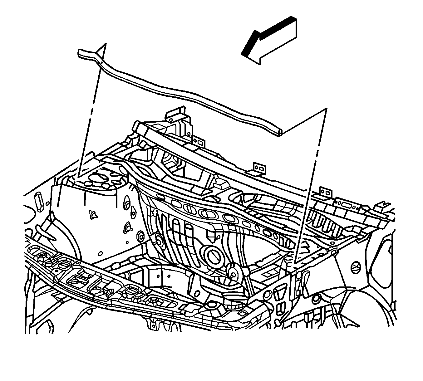
- Pull each end of the hood rear seal away from the cowl panel flange near both strut towers.
- Replace 2 strut bolts with studs GM P/N 11519137 on right and left sides of the vehicle for installation of support fixture.
- Install the J-28467-13 (1) and J 28467-5 strut tower adapter (2) to the top of the right strut tower.
- Install the J-28467-13 (2) and J 28467-5 strut tower adapter (1) to the top of the left strut tower.
- Install a 127 cm (50 in) engine support fixture cross bar (2) transversely across the vehicle between both J 28467-5 strut tower adapters.
- Insert safety pins (1, 3) through the J 28467-5 strut tower adapters and the cross bar (2) to prevent movement.
- Position a 58 cm (23 in) engine support fixture cross bar (1) longitudinally with J 36462-A leg assembly (3) next to the rear engine lift bracket.
- Install a J 28467-1A clamp (2) to secure the longitudinal mounted cross bar to the transverse mounted cross bar.
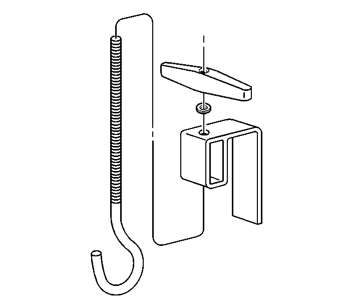
- Insert a J 28467-7A lift hook through a J 28467-6 bracket and install a J 28467-34 wing nut.
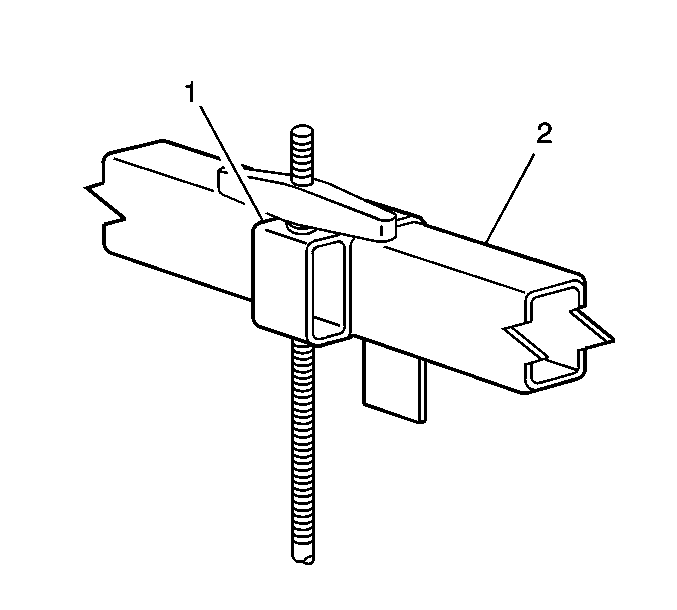
- Install the lift hook and bracket assembly (1) to the longitudinal mounted cross bar (2).
- Position the J 28467-7A lift hook to the rear engine lift bracket (2).
- Tighten the J 28467-34 wing nut (1) until all free slack is removed from the J 28467-7A bolt hook.
- Position a 58 cm (23 in) engine support fixture cross bar (3) longitudinally with J 36462-A leg assembly (4) next to the front engine lift bracket.
- Install a J 28467-1A clamp to secure the longitudinal mounted cross bar to the transverse mounted cross bar.
- Insert a J 28467-7A lift hook through a J 28467-6 bracket and install a J 28467-34 wing nut.
- Install the lift hook and bracket assembly (1) to the longitudinal mounted cross bar (2).
- Position the J 28467-7A bolt hook (1) to the front engine lift bracket.
- Tighten the J 28467-34 wing nut (2) until all free slack is removed from the J 28467-7A lift hook (1).
- Evenly tighten both wing nuts until the engine weight is supported by the engine support fixture and no longer carried by the engine mounts.
- After removing the engine support fixture, replace the temporary strut studs with the original strut bolts.

Notice: Refer to Fastener Notice in the Preface section.

Tighten
Tighten the studs to 25 N·m (18 lb ft).


Important: If 58 cm (23 in) length engine support cross bar is not available it may be necessary to remove the vehicle hood for additional clearance if a longer cross bar is to be substituted.


Important: If 58 cm (23 in) length engine support cross bar is not available it may be necessary to remove the vehicle hood for additional clearance if a longer cross bar is to be substituted.


Notice: Refer to Fastener Notice in the Preface section.

Tighten
Tighten the studs to 25 N·m (18 lb ft).
