Callout
| Component Name
|
|
Caution: Refer to Brake Fluid Irritant Caution in the Preface section.
Notice: Refer to Brake Fluid Effects on Paint and Electrical Components Notice in the Preface section.
Notice: Always connect or disconnect the wiring harness connector from the EBCM/EBTCM
with the ignition switch in the OFF position. Failure to observe this precaution
could result in damage to the EBCM/EBTCM.
Preliminary Procedures
- Place the ignition switch in the OFF position.
- Clean the brake pipe fittings of any dirt or debris.
- Remove the underhood electrical center bracket. Refer to
Underhood Electrical Center or Junction Block Bracket Replacement
.
- Place a clean cloth under the brake modulator assembly to catch any brake fluid loss.
|
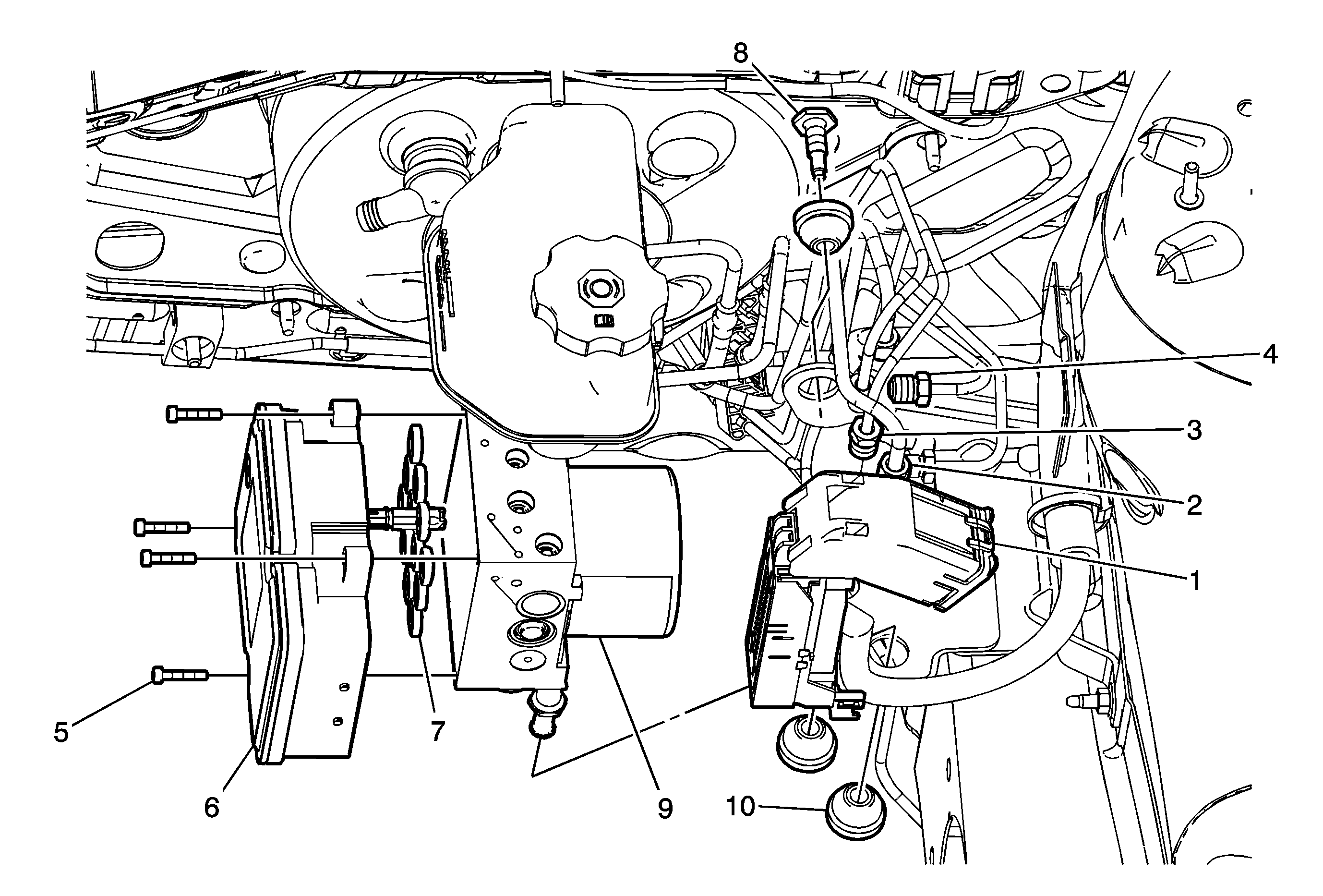
1
| Electronic Brake Control Module (EBCM) Electrical Connector
Tip
Release the locking tab and rotate the electrical connector cover upward to release. |
2
| Master Cylinder Brake Pipe Fitting (Qty: 2)
Notice: Refer to Fastener Notice in the Preface section.
Tip
| • | Cap the brake pipe fittings to prevent brake fluid loss and contamination. |
| • | Plug the brake modulator assembly inlet ports to prevent brake fluid loss and contamination. |
Tighten
21 N·m (16 lb ft) |
3
| Front Brake Pipe Fitting (Qty: 2)
Tip
| • | Cap the brake pipe fittings to prevent brake fluid loss and contamination. |
| • | Plug the brake modulator assembly outlet ports to prevent brake fluid loss and contamination. |
Tighten
21 N·m (16 lb ft) |
4
| Rear Brake Pipe Fitting (Qty: 2)
Tip
| • | Cap the brake pipe fittings to prevent brake fluid loss and contamination. |
| • | Plug the brake modulator assembly outlet ports to prevent brake fluid loss and contamination. |
Tighten
21 N·m (16 lb ft) |
5
| EBCM to Brake Pressure Modulator Valve (BPMV) Screw (Qty: 4)
Tip
Tighten the screws in a cross pattern.
Tighten
3 N·m (27 lb in) |
6
| Electronic Brake Control Module (EBCM)
|
7
| EBCM to BPMV Seal (Qty: 12)
|
8
| Brake Modulator Assembly Bolt
Tighten
20 N·m (15 lb ft) |
9
| Brake Pressure Modulator Valve
Tip
| • | Turn the ignition switch to the ON position. DO NOT start the engine. |
| • | Observe the feel of the brake pedal after performing the diagnostic system check. If the pedal now feels spongy, air may have been in the secondary circuit of the brake modulator assembly, which may have been introduced into the primary circuit.
If the pedal feels spongy, perform the
Antilock Brake System Automated Bleed Procedure
. |
|
10
| Brake Modulator Assembly Insulator (Qty: 3)
|