For 1990-2009 cars only
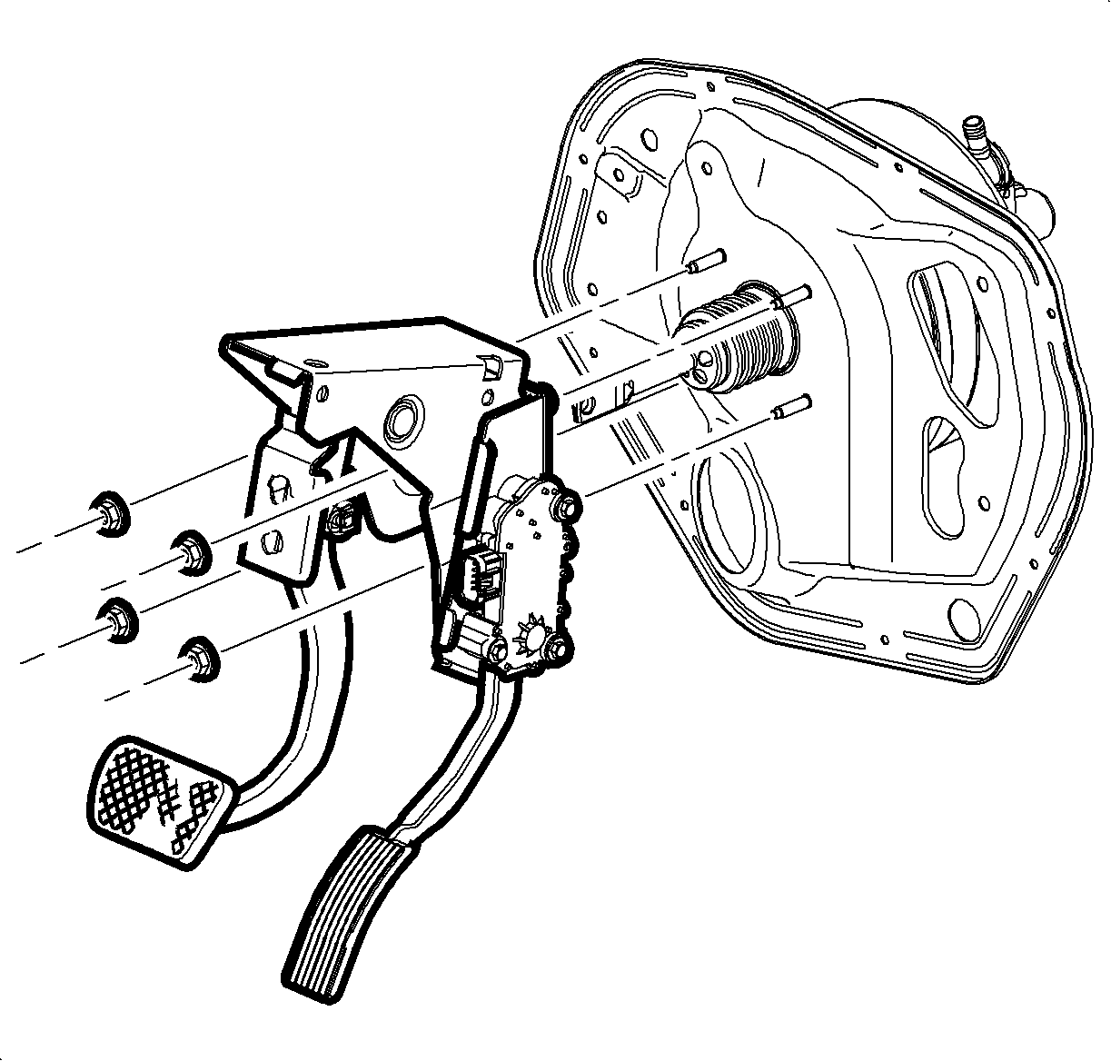
Removal Procedure
- Disconnect and remove the battery. Refer to Battery Replacement in Engine Electrical.
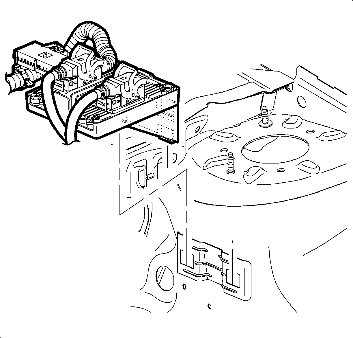
- Remove and position aside the underhood electrical center. Refer to Underhood Electrical Center or Junction Block Replacement in Wiring Systems.
- Remove the battery tray. Refer to Battery Tray Replacement in Engine Electrical.
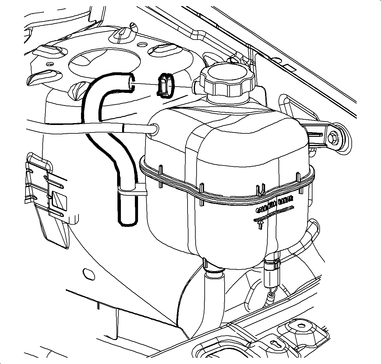
- Disconnect the coolant surge hose from the surge tank and position aside.
- Remove the master cylinder mounting nuts. Do NOT disconnect the brake pipes from the master cylinder.
- Carefully pull the master cylinder away from the vacuum booster and position aside.
- Disconnect the vacuum booster check valve and hose assembly from the booster. Refer to Vacuum Brake Booster Check Valve and/or Hose Replacement .
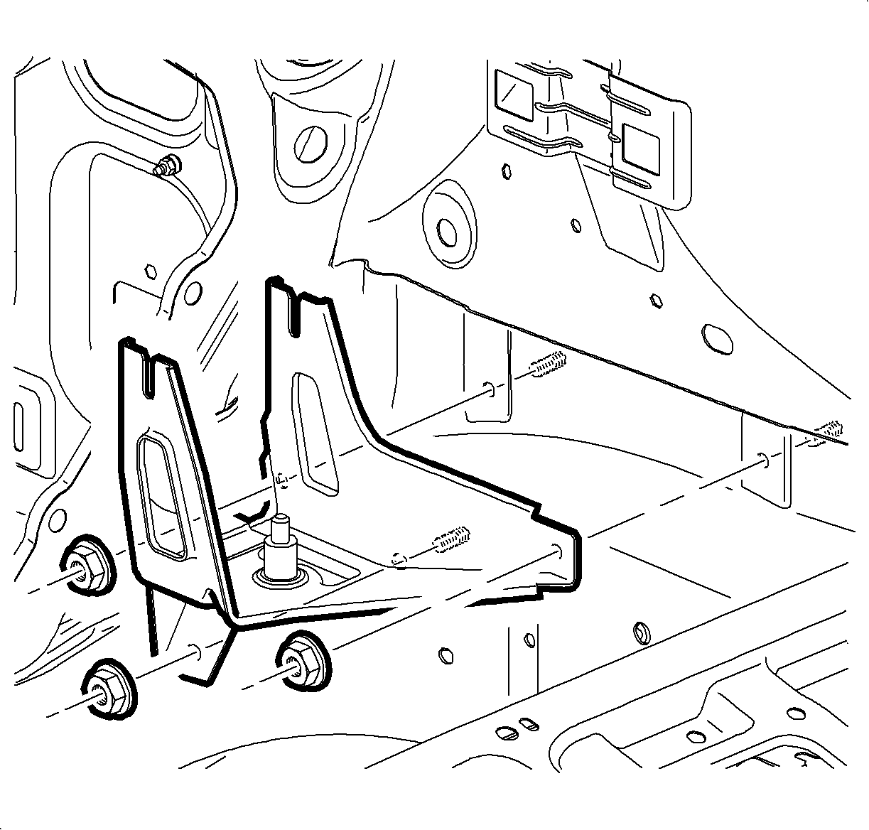
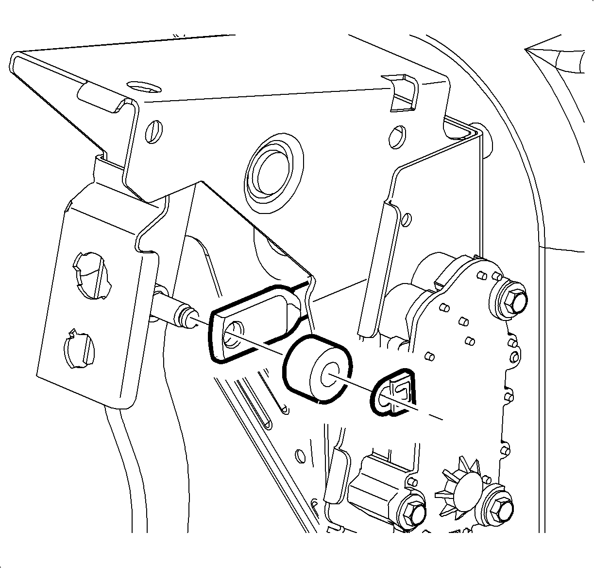
- Without disconnecting the electrical connectors, remove the transmission control module (TCM) with the bracket from the bracket on the strut tower and position aside on top of the engine. Refer to Transmission Control Module Replacement in Automatic Transaxle - AF33-5.
- Remove the brake modulator assembly, if equipped. Refer to Brake Pressure Modulator Valve Assembly Replacement in Antilock Brake System.
- Remove the brake modulator valve bracket, if equipped. Refer to Brake Pressure Modulator Valve Bracket Replacement in Antilock Brake System.
- Remove the brake booster push rod-to-brake pedal retaining clip.
- Remove the foam washer from the brake pedal assembly.
- Remove the brake booster mounting nuts.
- Disengage the brake booster from the front of dash and the brake pedal bracket. Maneuver the booster toward the center of the vehicle in order to ease removal.

Important: Ensure that the foam insulator on the mounting surface of the brake booster withdraws with the booster.
Installation Procedure
- Install the foam insulator the vacuum brake booster.
- Install the brake booster to the vehicle.
- Install, but do not tighten, the booster mounting nuts.
- Lightly lubricate the booster push rod pivot pin on the brake pedal with silicone lubricant.
- Install the booster push rod to the pivot pin on the brake pedal.
- Install the foam washer to the pivot pin.
- Install the brake booster push rod retaining clip.
- Fully seat the brake booster to the front of dash and the brake pedal assembly.
- Tighten the vacuum brake booster mounting nuts.
- Install the brake modulator valve bracket, if equipped. Refer to Brake Pressure Modulator Valve Bracket Replacement in Antilock Brake System.
- Install the brake modulator assembly, if equipped. Refer to Brake Pressure Modulator Valve Assembly Replacement in Antilock Brake System.
- Reposition the TCM and bracket to the bracket on the strut tower. Refer to Transmission Control Module Replacement in Automatic Transaxle - AF33-5.
- Install the vacuum booster check valve and hose assembly to the booster.
- Reposition and install the master cylinder to the booster. Refer to Master Cylinder Replacement .
- Install the coolant surge hose and clamp to the surge tank.
- Install the battery tray. Refer to Battery Tray Replacement in Engine Electrical.
- Install the underhood electrical center. Refer to Underhood Electrical Center or Junction Block Replacement in Wiring Systems.
- Install and connect the battery. Refer to Battery Replacement in Engine Electrical.
- If necessary, bleed the brake system. Refer to Hydraulic Brake System Bleeding .
Notice: Refer to Fastener Notice in the Preface section.
Tighten
Tighten the nuts to 25 N·m (18 lb ft).