Removal Procedure
- Remove the fuel pump fuse.
- Start the engine and repeat cranking until the remaining fuel in the fuel line is all consumed.
- Disconnect the negative battery cable.
- Drain the engine coolant. Refer to Cooling System Draining and Filling in Engine Cooling.
- Drain the engine oil.
- Drain the transaxle oil.
- Drain the power steering oil.
- Recover the refrigerant. Refer to Refrigerant Recovery and Recharging in Heating, Ventilation, and Air Conditioning.
- Remove the engine assembly. Refer to Engine Replacement .
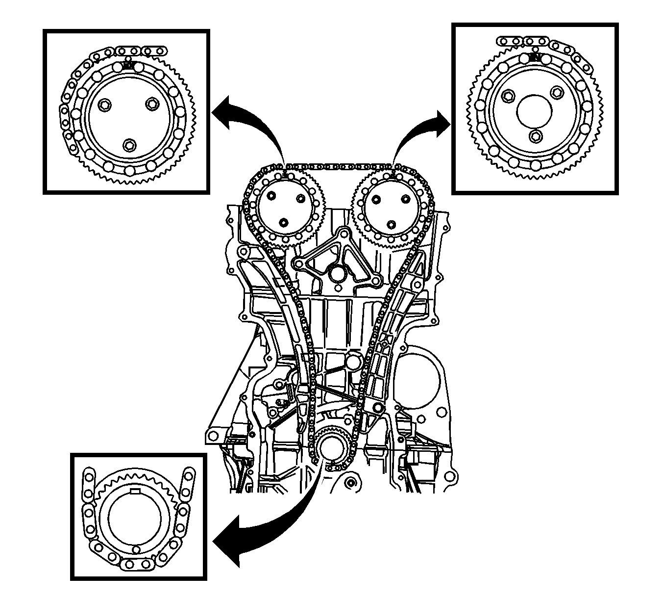
- Remove the timing chain. Refer to Timing Chain and Sprocket Replacement .
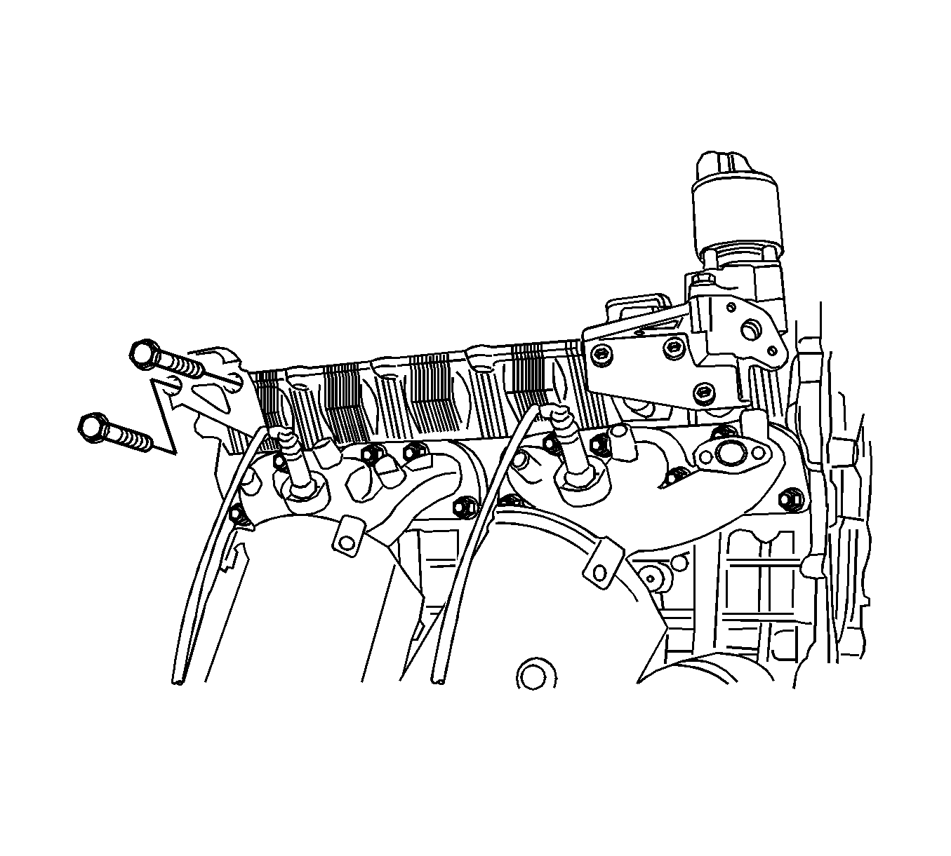
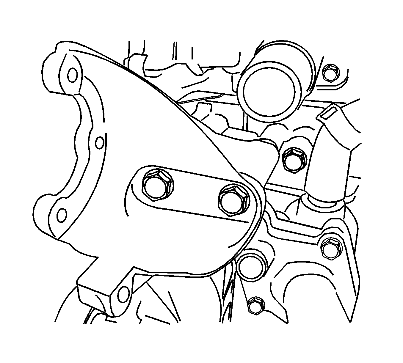
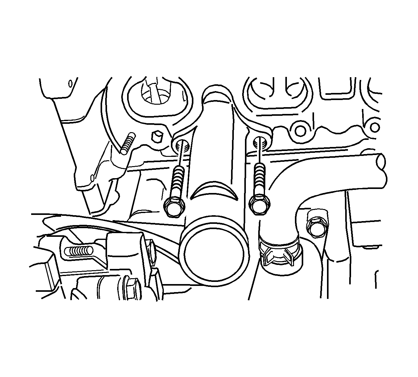
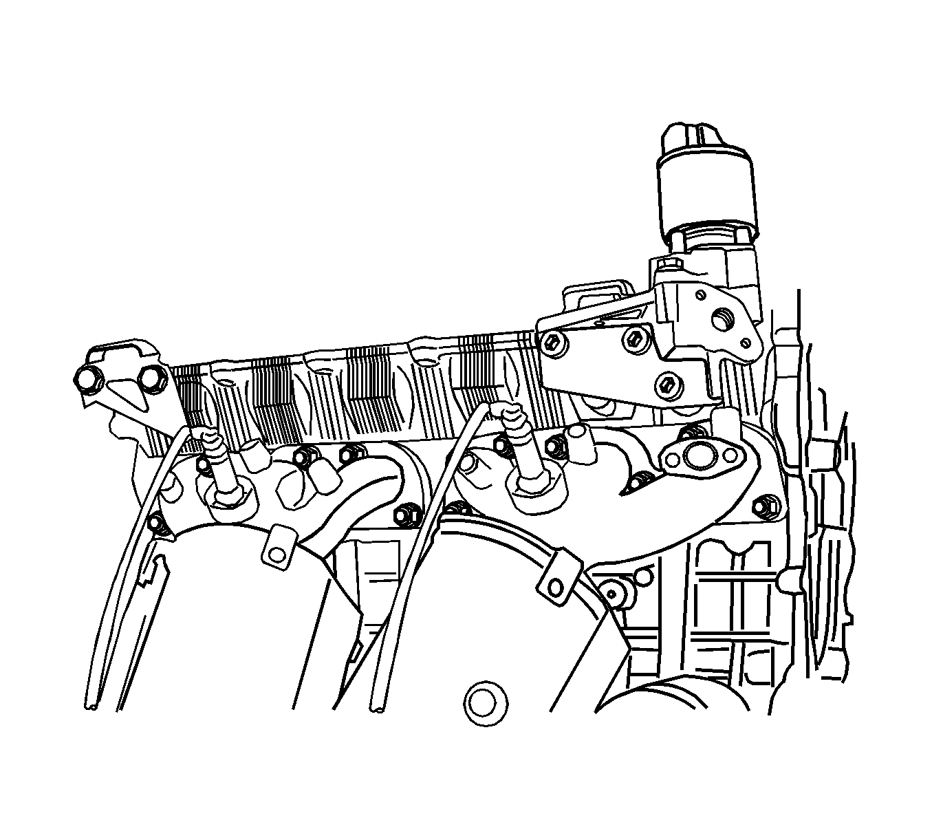
- Remove the intake manifold support bracket.
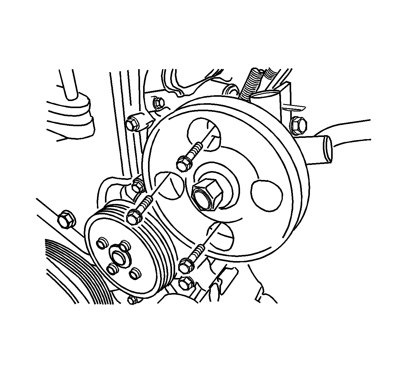
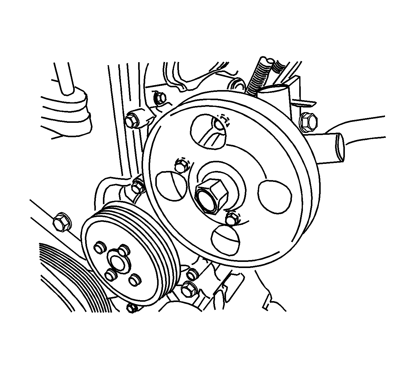
- Remove the power steering pump.
- Remove the alternator. Refer to Generator Replacement in Engine Electrical.
- Remove the upper pad bracket bolts and the upper pad bracket.
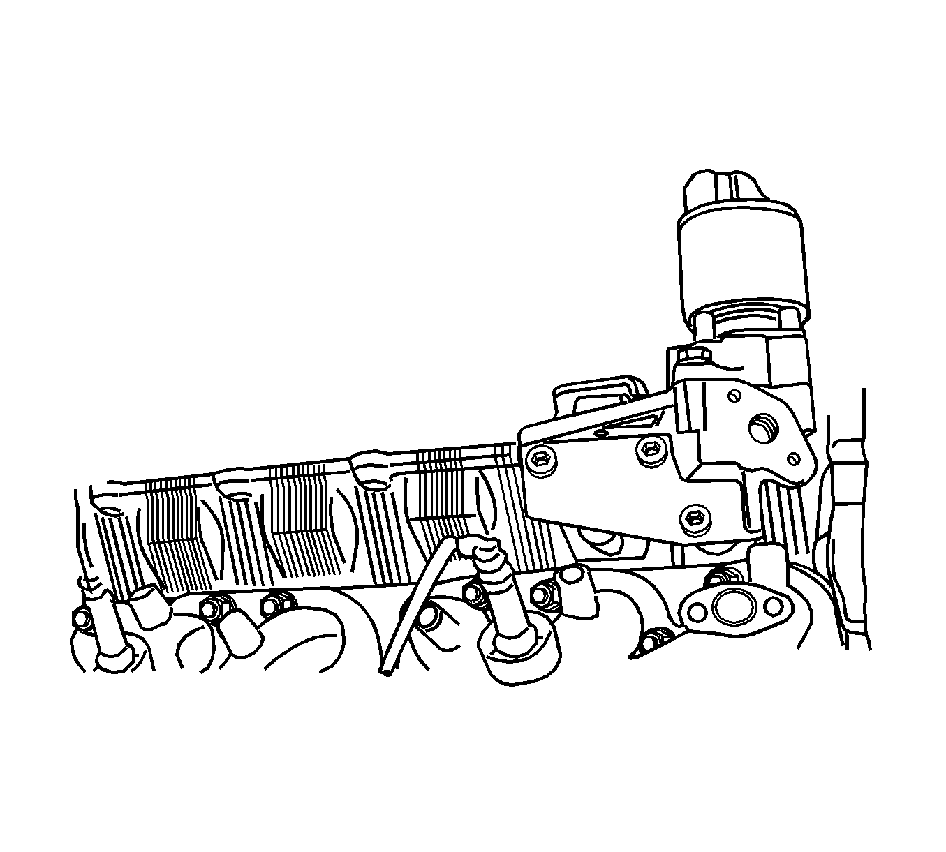
- Remove the exhaust gas recirculation (EGR) valve. Refer to Exhaust Gas Recirculation Valve Replacement in Engine Controls-2.5L.
- Remove the EGR pipes. Refer to Exhaust Gas Recirculation Valve Pipe Replacement in Engine Controls-2.5L.
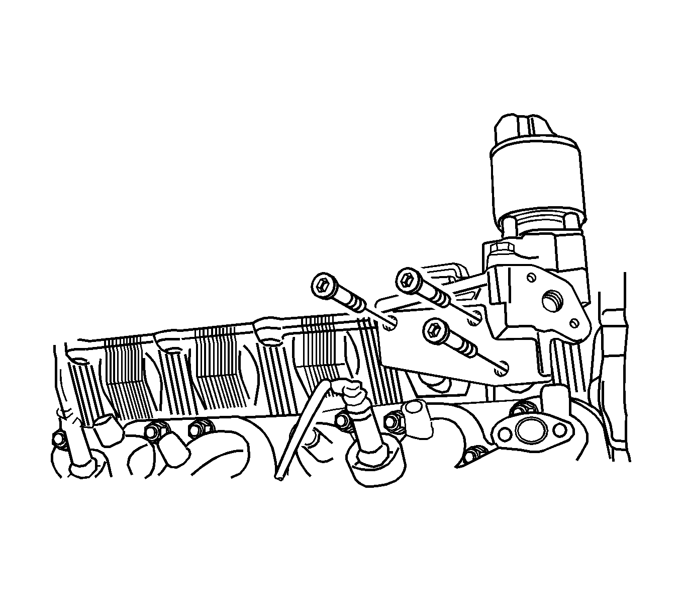
- Remove the EGR adapter.
- Remove the heater pipe.
- Remove the exhaust manifold. Refer to Exhaust Manifold Removal .
- Remove the exhaust manifold gasket.
- Remove the camshaft position (CMP) sensor. Refer to Camshaft Position Sensor Replacement in Engine Controls-2.5L.
- Remove the engine coolant temperature (ECT) sensor. Refer to Engine Coolant Temperature Sensor Replacement in Engine Controls-2.5L.
- Remove the coolant outlet port.
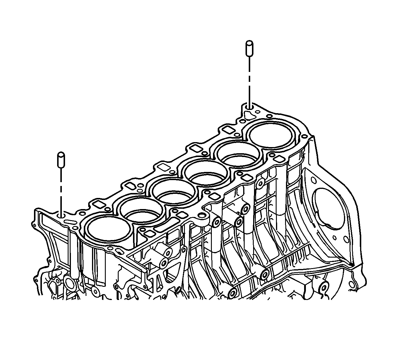
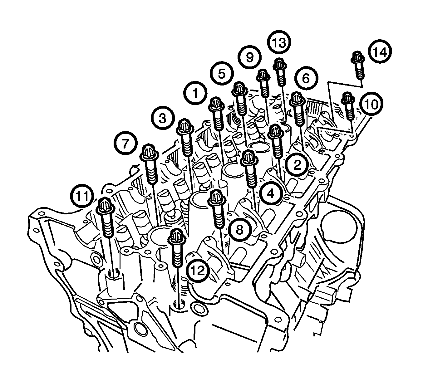
- Remove the cylinder head bolts in sequence shown and the cylinder head.
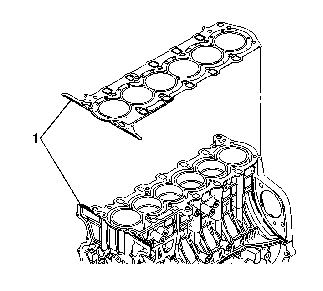
- Remove the cylinder head gasket.
- Remove the liquid gasket.
Caution: Refer to Battery Disconnect Caution in the Preface section.

Notice: Use extreme care when removing the cylinder head to prevent any engine oil , dirt, or coolant from entering the engine. Damage to the engine could result.
Installation Procedure
- Clean the contact surfaces between the cylinder head and the cylinder block.
- Install the dowel pins.
- Apply the RTV sealer Loctite® 5900-M8585, GM P/N 12346286 or Canadian P/N 10953472 on the surface of the cylinder block (1) as shown in the illustration.
- Install the cylinder head gasket.
- Apply the RTV sealer Loctite® 5900-M8585, GM P/N 12346286 or Canadian P/N 10953472 on the upper surface of the cylinder head gasket (1) as shown in the illustration.
- Install the cylinder head.
- Tighten the cylinder head bolts gradually and in the sequence shown.
- Install the coolant outlet port.
- Install the ECT sensor. Refer to Engine Coolant Temperature Sensor Replacement in Engine Controls-2.5L.
- Instal the CMP sensor. Refer to Camshaft Position Sensor Replacement in Engine Controls-2.5L.
- Discard the used exhaust manifold gasket and replace with a new one.
- Install the exhaust manifold. Refer to Exhaust Manifold Removal .
- Install the heater pipe.
- Install the EGR adapter.
- Install the EGR pipes. Refer to Exhaust Gas Recirculation Valve Pipe Replacement in Engine Controls-2.5L.
- Install the EGR valve. Refer to Exhaust Gas Recirculation Valve Replacement in Engine Controls-2.5L.
- Install the upper pad bracket.
- Install the alternator. Refer to Generator Replacement in Engine Electrical.
- Install the power steering pump.
- Install the intake manifold support bracket.
- Install the timing chain and the timing chain cover. Refer to Timing Chain and Sprocket Replacement .
- Install the engine assembly. Refer to Engine Replacement .
- Install the fuel pump fuse.
- Connect the negative battery cable.
- Refill the crankcase with engine oil.
- Refill the engine coolant system. Refer to Cooling System Draining and Filling in Engine Cooling.
- Fill and bleed the power steering system Refer to Power Steering System Bleeding in Power Steering System.
- Refill the A/C System. Refer to Refrigerant Recovery and Recharging in Heating, Ventilation, and Air Conditioning.
Notice: Refer to Fastener Notice in the Preface section.
Tighten
Tighten the cylinder head bolts to 20 N·m (15 lb ft). After finishing the initial tightening, tighten all the cylinder head bolts to 25 N·m (18 lb ft) and turn the bolts
another 2 turns of 70 degrees.
Tighten
Tighten the coolant outlet port retaining bolts to 10 N·m (89 lb in).
Tighten
Tighten the EGR adapter retaining bolts to 20 N·m (15 lb ft).
Tighten
Tighten the upper pad bracket bolts to 45 N·m (33 lb ft).
Tighten
Tighten the power steering pump retaining bolts to 25 N·m (18 lb ft).
Tighten
Tighten the intake manifold support bracket bolt to 25 N·m (18 lb ft).