For 1990-2009 cars only
Removal Procedure
- Remove the wheel.
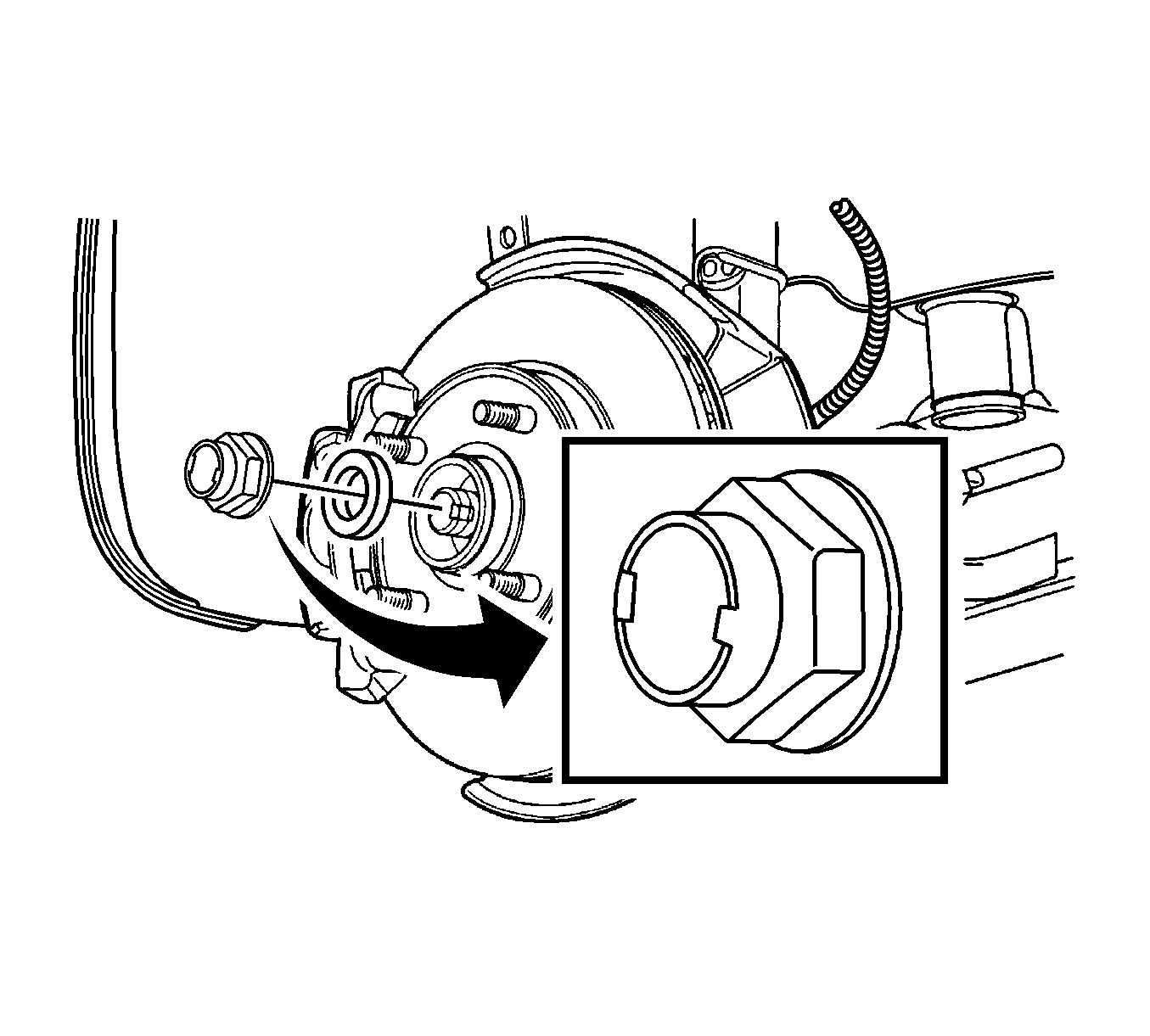
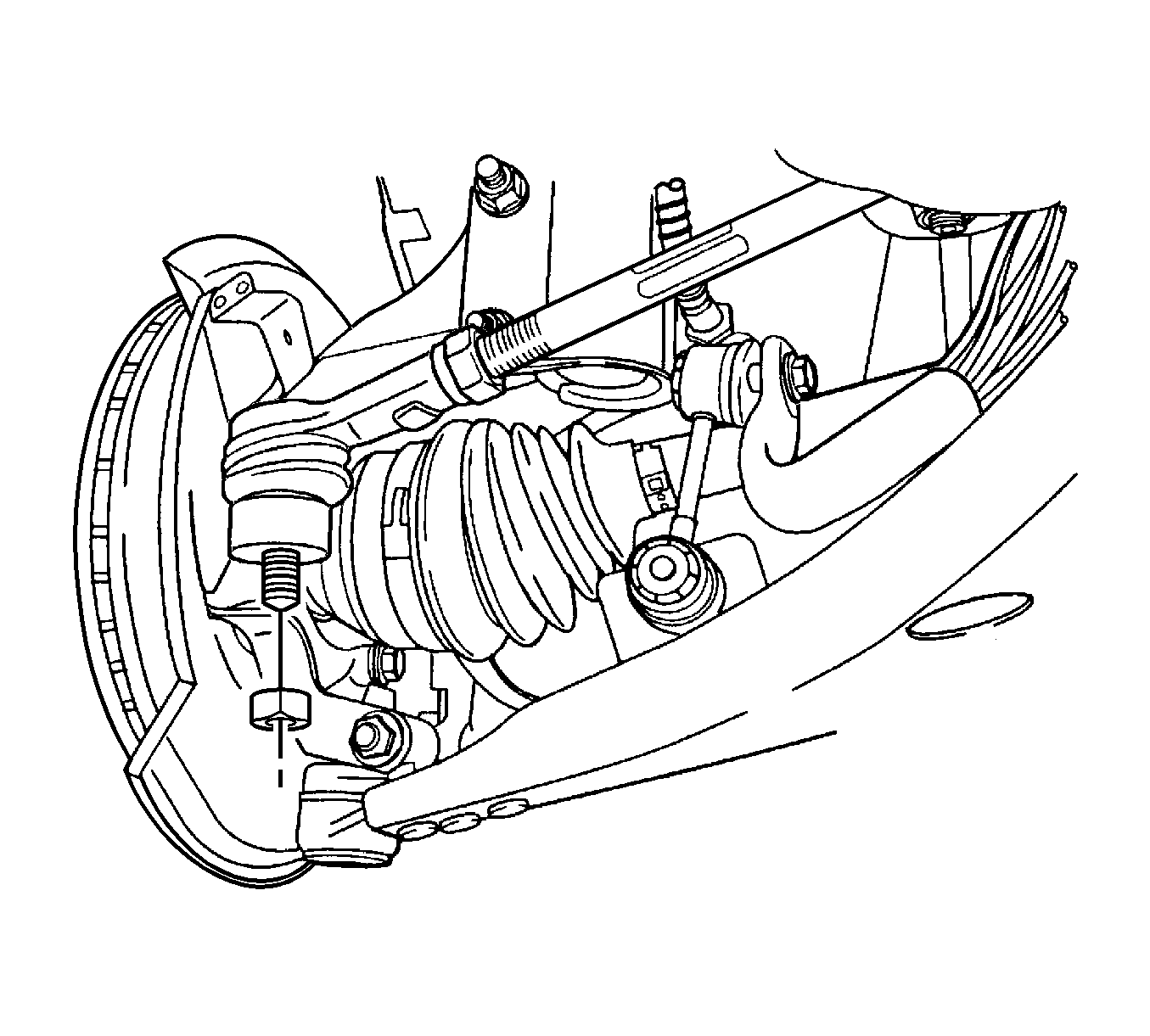
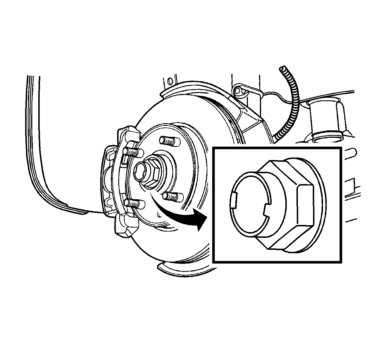
- Remove the caulking nut and washer.
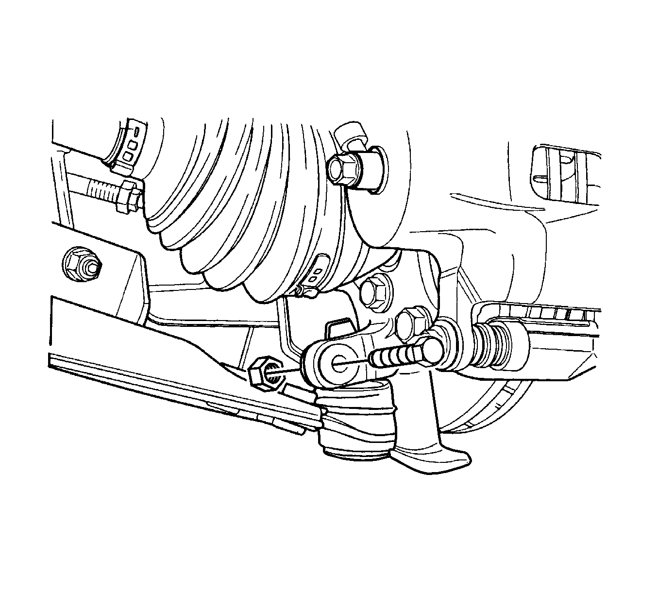
- Remove the outer tie rod. Refer to Rack and Pinion Outer Tie Rod End Replacement .
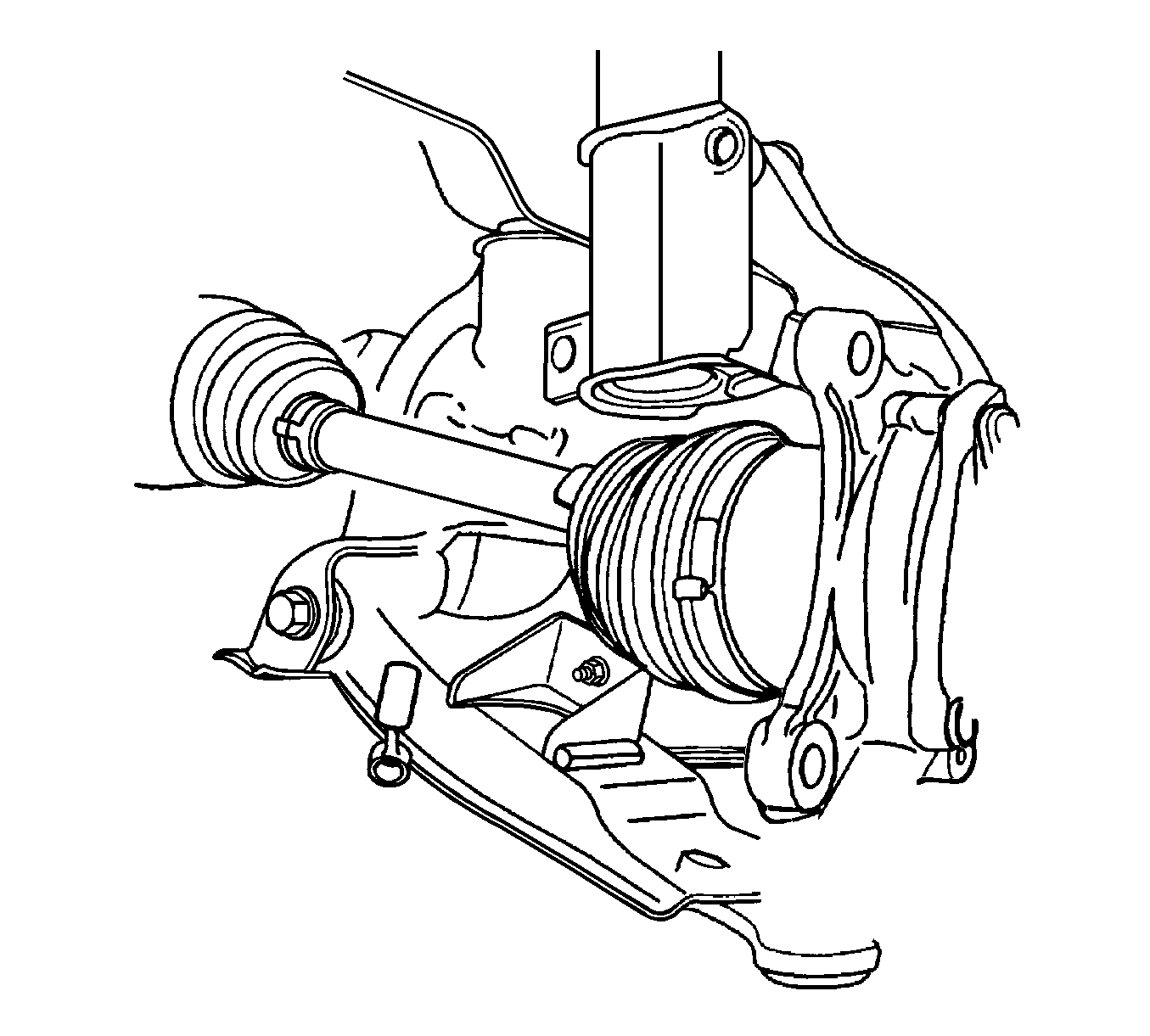
- Disconnect the control arm ball joint.
- Remove the brake caliper. Refer to Front Brake Caliper Replacement .
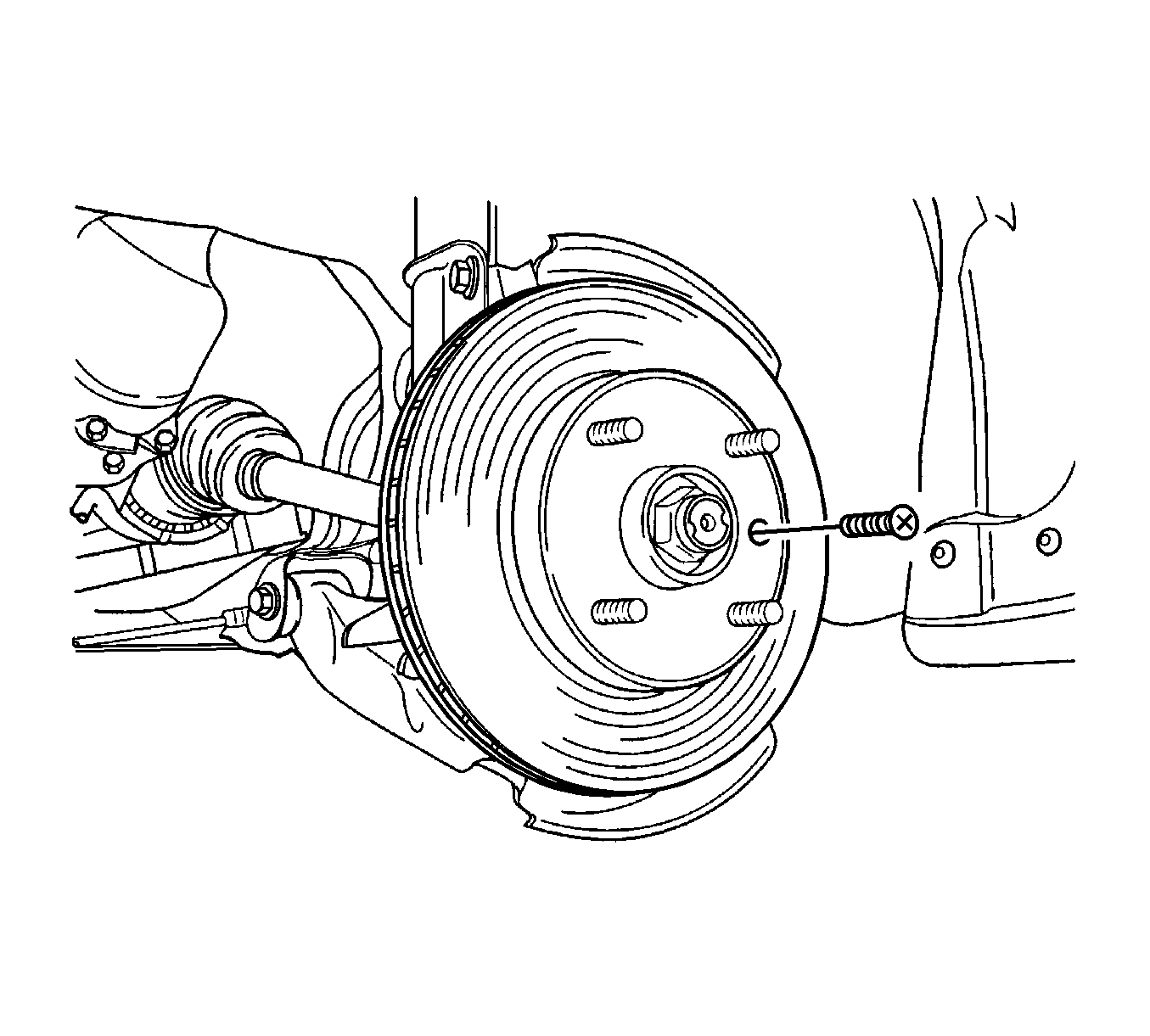
- Remove the detent screw from the brake disc. Remove the disc.
- Remove the splash shield. Refer to Front Brake Shield Replacement .
- Remove the front strut bolts.
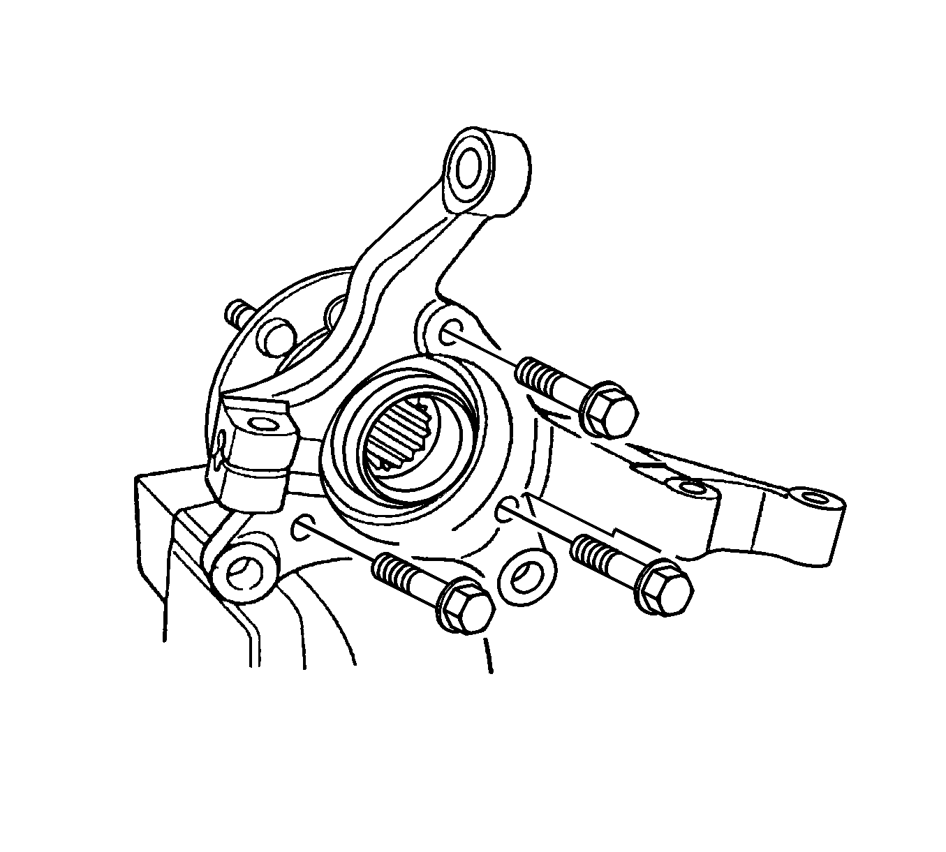
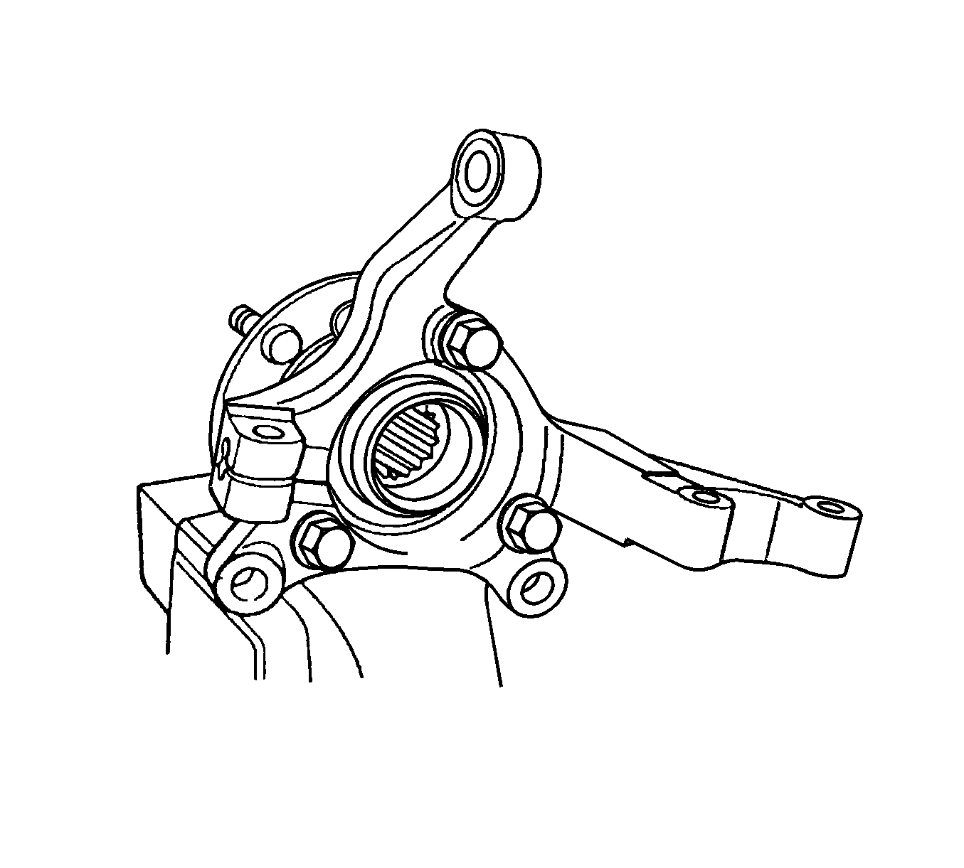
- Remove the knuckle, hub assembly.
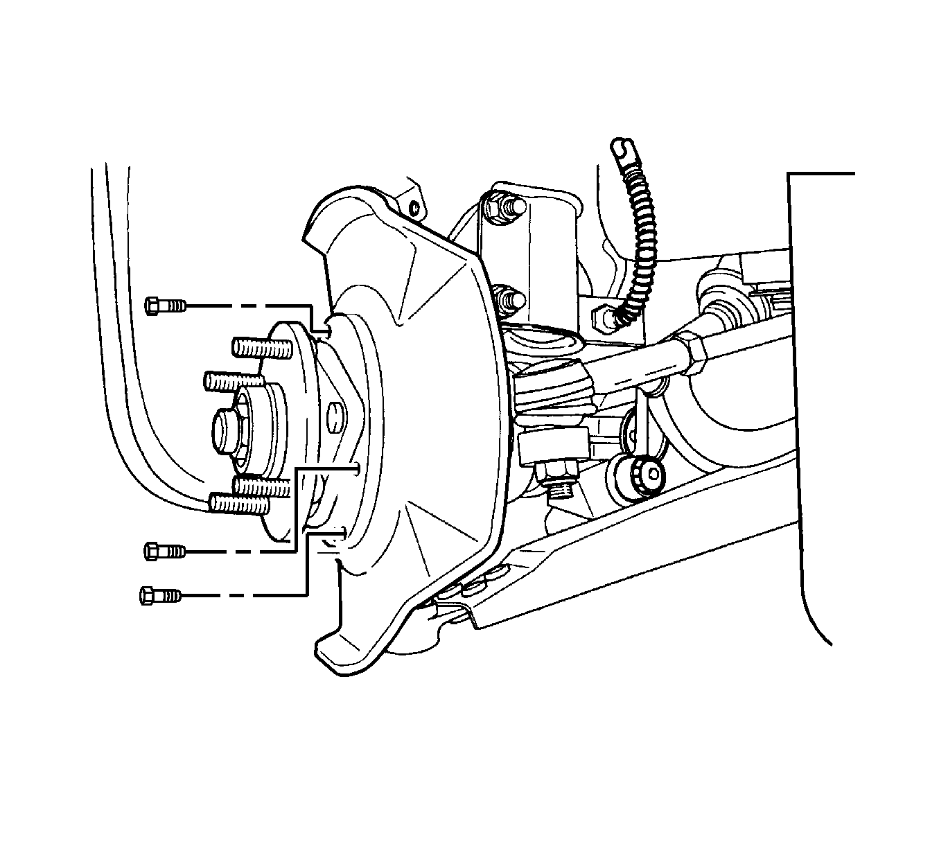
- Remove the hub bolts from the knuckle and separate the hub from the knuckle.
Installation Procedure
- Install the hub bolts.
- Install the splash shield and front strut bolts. Refer to Front Brake Shield Replacement .
- Install the detent screw and disc.
- Install the brake caliper. Refer to Front Brake Caliper Replacement .
- Install the control arm ball joint bolt.
- Install the outer tie rod bolt. Refer to Rack and Pinion Outer Tie Rod End Replacement .
- Install the washer and the caulking nut onto the axle shaft.
- Bleed the air out of the brake system. Refer to Hydraulic Brake System Bleeding .
Notice: Refer to Fastener Notice in the Preface section.
Tighten
Tighten the hub bolts to 95 N·m (70 lb ft).
Tighten
Tighten the splash shield bolts to 10 N·m (89 lb in).
Tighten
Tighten the detent screw to 5 N·m (44 lb in).
Tighten
Tighten the control arm ball joint bolt to 110 N·m (81 lb ft).
Tighten
Tighten the outer tie rod bolt to 50 N·m (37 lb ft).
Tighten
Tighten the caulking nut onto the axle shaft to 280 N·m (207 lb ft).
