Rear Bumper Impact Bar Replacement Corvette
Tools Required
J 42058 Frame Adapter Clamp
Removal Procedure
- Disable the SIR system. Refer to SIR Disabling and Enabling .
- Disconnect the negative battery cable. Refer to Battery Negative Cable Disconnection and Connection .
- Remove all related panels and components.
- Remove or reposition the wiring to avoid damage.
- Repair as much of the damage as possible to the factory specifications.
- Use J 42058 to secure the vehicle if pulling and straightening are required.
- Note the location and remove the sealers and anti-corrosion materials from the repair area. Refer to Anti-Corrosion Treatment and Repair .
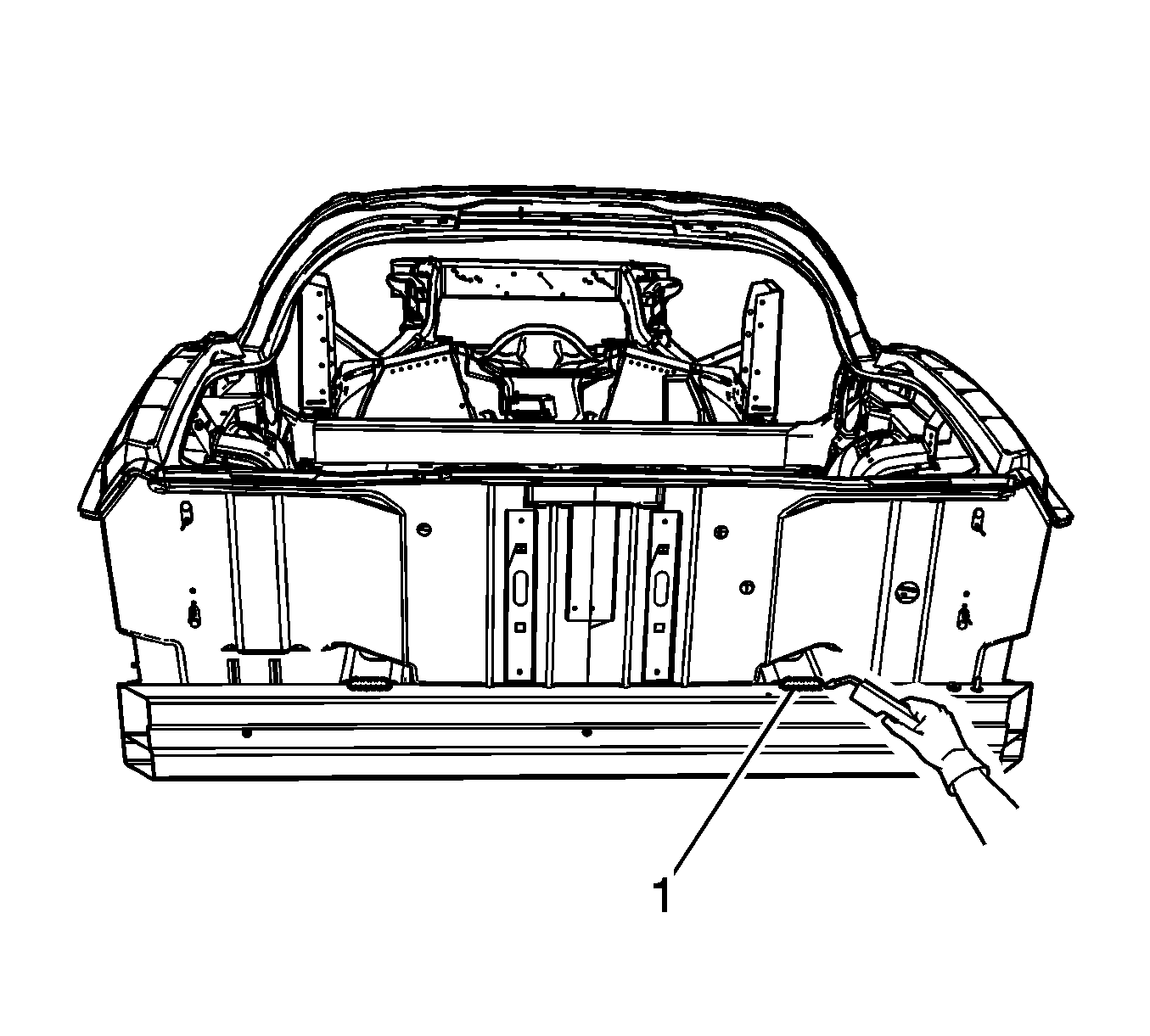
- Apply heat and pry apart to separate the impact bar from the rear compartment panel.
- Cut the welds around the perimeter of the frame rail ends. Cut the welds favoring the impact bar side of the joint.
- Remove the damaged impact bar.
- Extract pieces of the impact bar which are left attached to the rail ends.
- Straighten and deburr the rail ends. Keep the perimeter and shape of the rail ends as original as possible.
Caution: Refer to Approved Equipment for Collision Repair Caution in the Preface section.
Important: Do not cut into the frame rails.
Installation Procedure
- Temporarily position the impact bar for proper fit and alignment.
- Clean and prepare all of the welded surfaces.
- Apply GM-approved Weld-Thru Coating or equivalent to all mating surfaces. Refr to Anti-Corrosion Treatment and Repair .
- Clean and prepare all bonding mating surfaces according to adhesive manufacturer's recommendations.
- Apply a consistent bead of structural adhesive to the top impact bar to bond to the rear compartment panel. Refer to Sheet Molded Compound (SMC) Panel Bonding .
- Position the bumper impact bar to the vehicle using 3-dimensional measuring equipment.
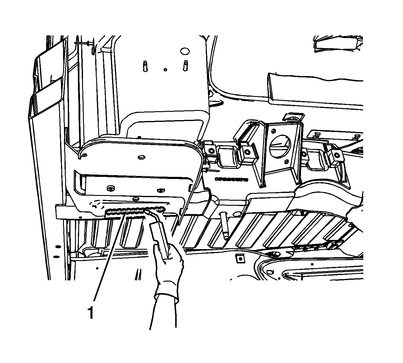
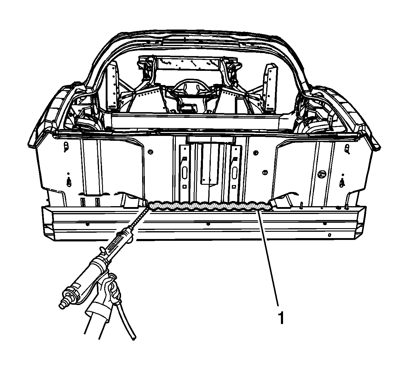
- Using a metal inert gas (MIG) welder, stitch weld the rear bar to the frame rail ends.
- Apply the sealers and anti-corrosion materials to the repair area. Refer to Anti-Corrosion Treatment and Repair .
- Paint the repair area. Refer to Basecoat/Clearcoat Paint Systems .
- Install all related panels and components.
- Connect the negative battery cable. Refer to Battery Negative Cable Disconnection and Connection .
- Enable SIR system. Refer to SIR Disabling and Enabling .
Important: DO NOT top coat the bonding surface of the rear bar. Use primer only on bonding surfaces. Refer to adhesive manufacturer's recommendations.
Important: If no trace of the original welds are present, follow the pattern specified for welding the side rails to the impact bar.
Rear Bumper Impact Bar Replacement Z06
Tools Required
J 42058 Frame Adapter Clamp
Removal Procedure
- Disable the SIR system. Refer to SIR Disabling and Enabling .
- Disconnect the negative battery cable. Refer to Battery Negative Cable Disconnection and Connection .
- Remove all related panels and components.
- Repair as much of the damage as possible to the factory specifications.
- Use J 42058 to secure the vehicle if pulling and straightening are required.
- Note the location and remove the sealers and anti-corrosion materials from the repair area. Refer to Anti-Corrosion Treatment and Repair .
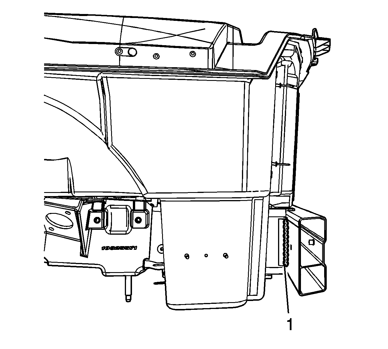
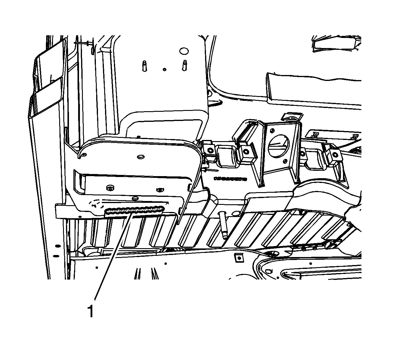
- Locate and remove all factory welds (1) attaching the rear bumper bar to the bottom of the rear frame rails. Note the location of the welds for installation of the new bumper bar.
- Locate and remove all factory welds (1) attaching the rear bumper bar to the outer and inner of the rear frame rails. Note the location of the welds for installation of the new bumper bar.
- Locate and remove all factory welds (1) attaching the rear bumper bar to the battery tray. Note the location of the welds for installation of the new bumper bar.
- Locate and remove all factory welds (1) attaching the rear bumper bar to the top of the rear frame rails. Note the location of the welds for installation of the new bumper bar.
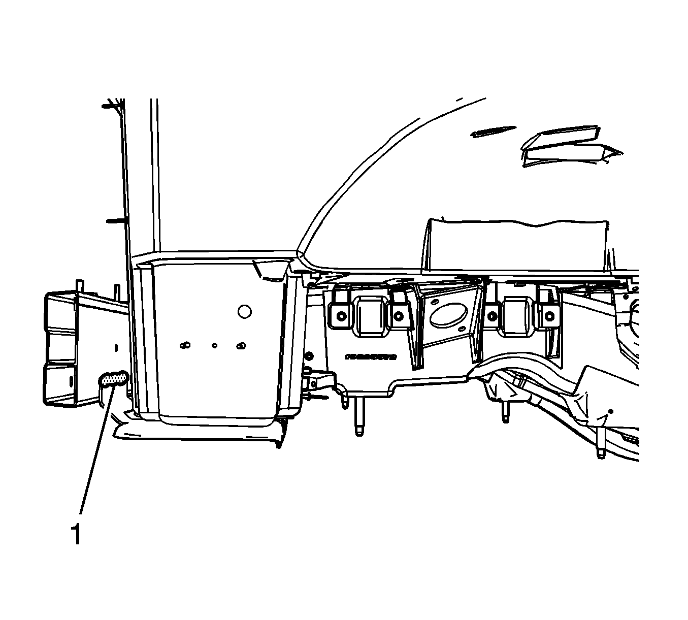
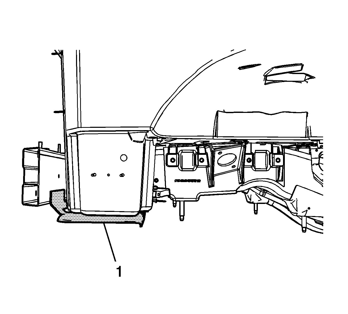
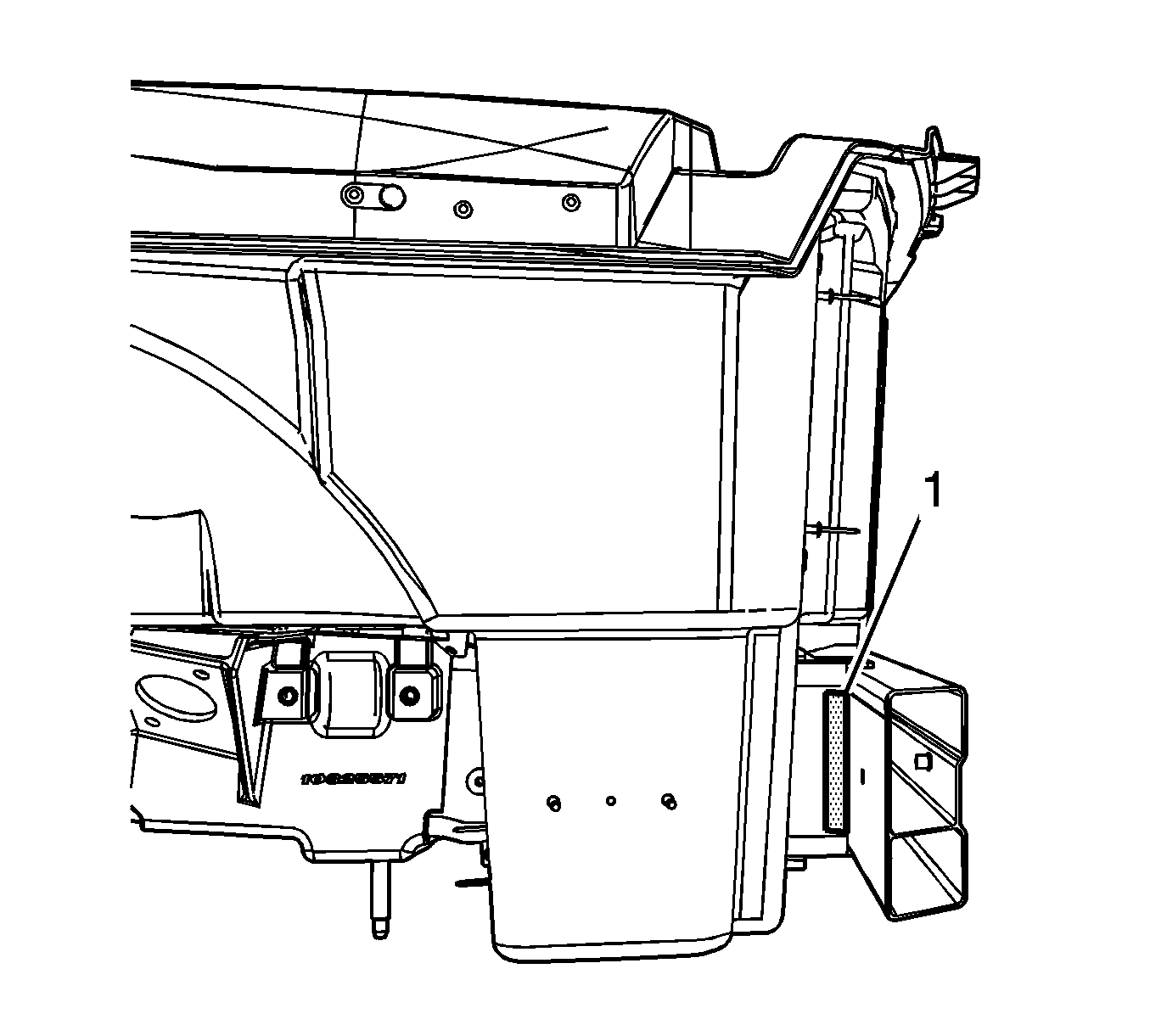
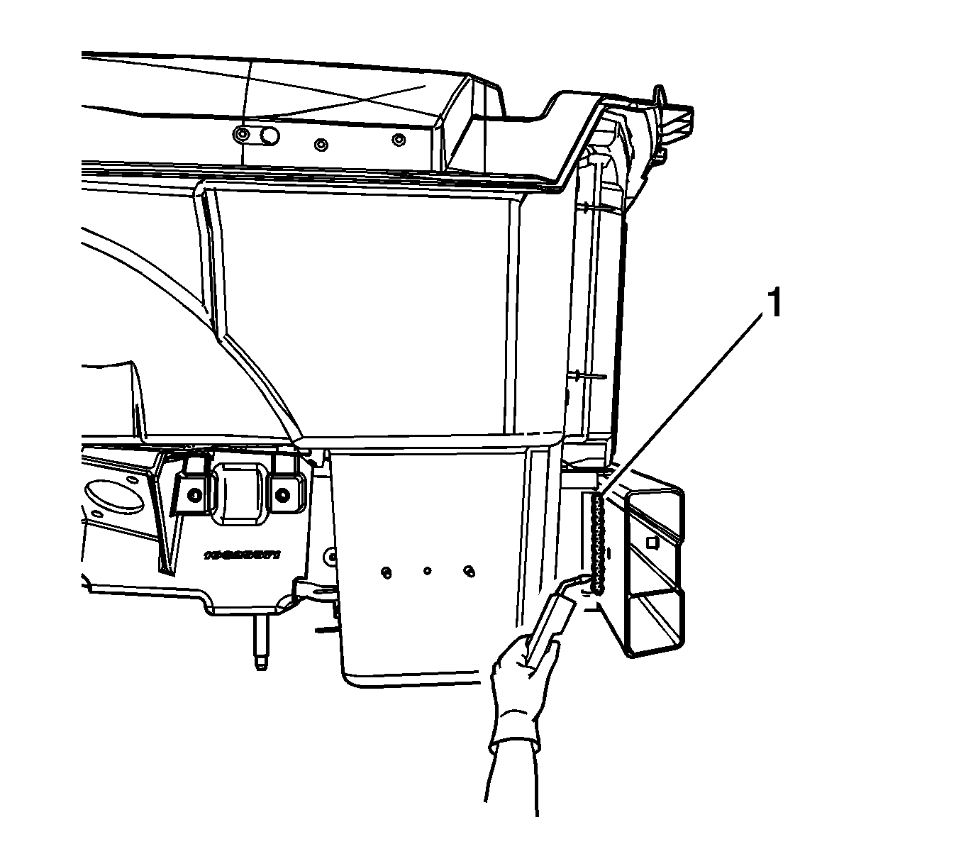
- Using a heat gun, detach the adhesive from the rear bar (1) to the rear compartment panel.
- Remove the damaged bumper bar.
- Locate and remove all factory welds (1) attaching the battery tray to the battery tray bracket. Note the location of the welds for installation of the battery tray.
- Using a heat gun, detach the adhesive from the battery tray to the rear compartment panel.
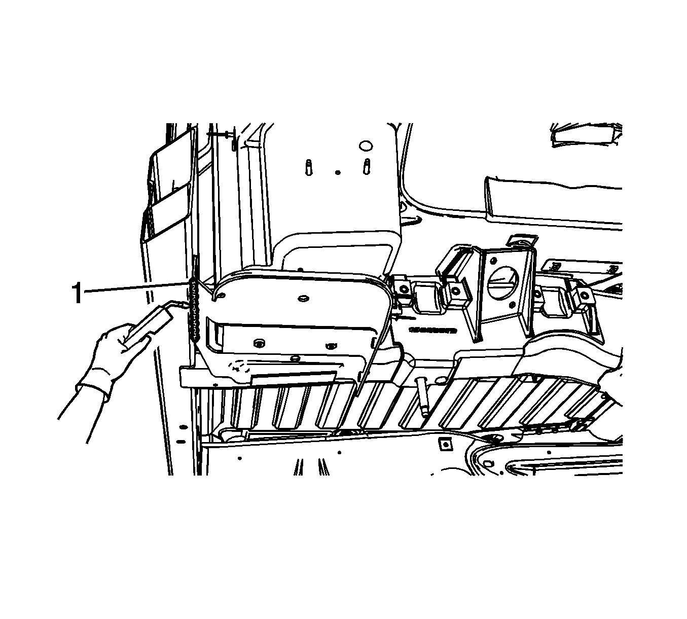
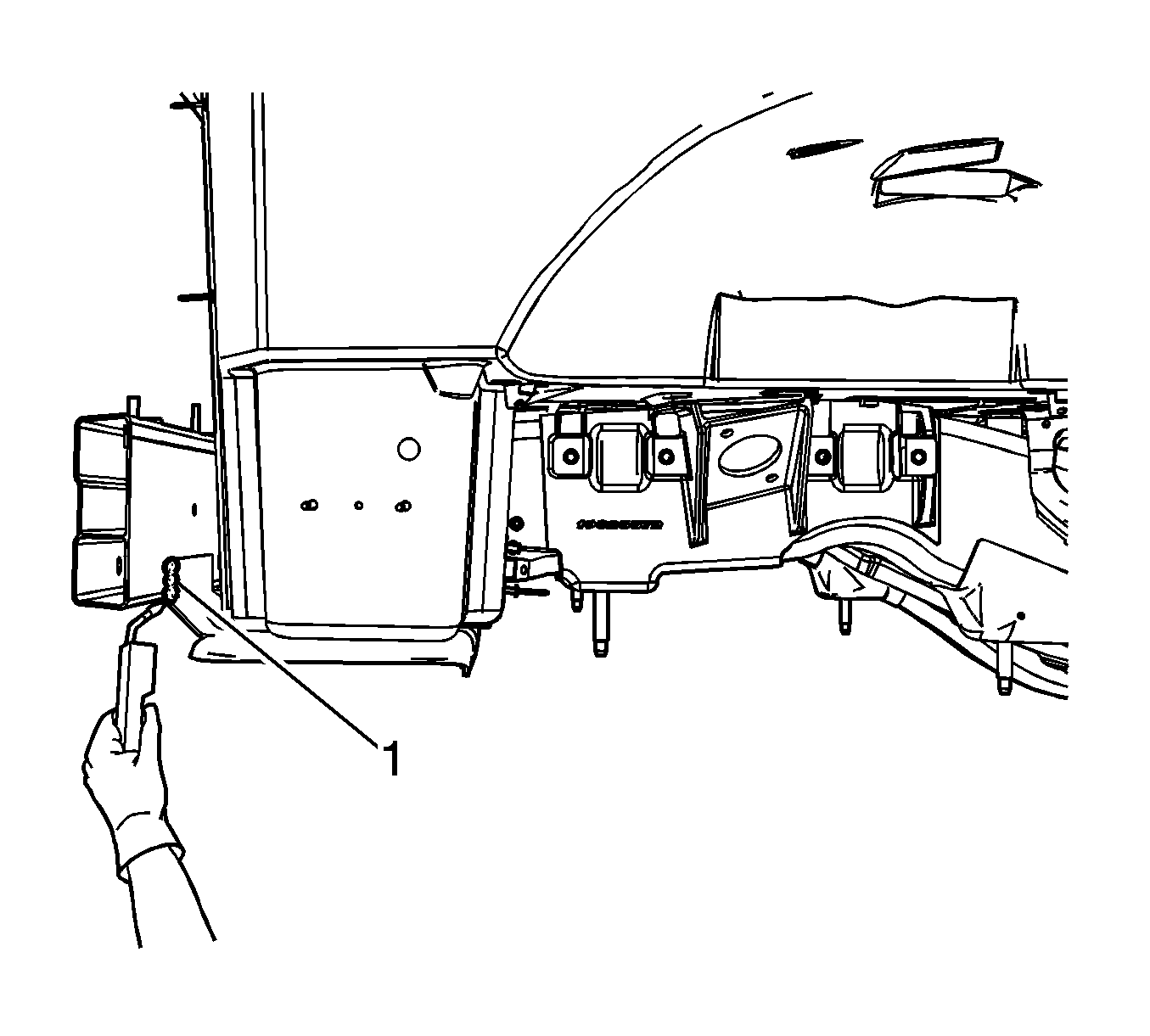
- Remove the battery tray (1).
- Remove pieces of the bumper bar which are left attached to the rail ends.
- Straighten and deburr the rail ends. Keep the perimeter and shape of the rail end as original as possible.
Caution: Refer to Approved Equipment for Collision Repair Caution in the Preface section.
Important:
• Hand tools, saw blades and abrasives used for aluminum repairs should be dedicated for aluminum only to prevent contamination. • When removing welds, favor the bumper bar side of the weld joint.
Installation Procedure
- Dry fit the bumper bar for proper fit and alignment before welding.
- Clean and prepare all of the welded mating surfaces.
- Install the rear bumper bar.
- Position the bumper bar to the vehicle using 3-dimensional measuring equipment.
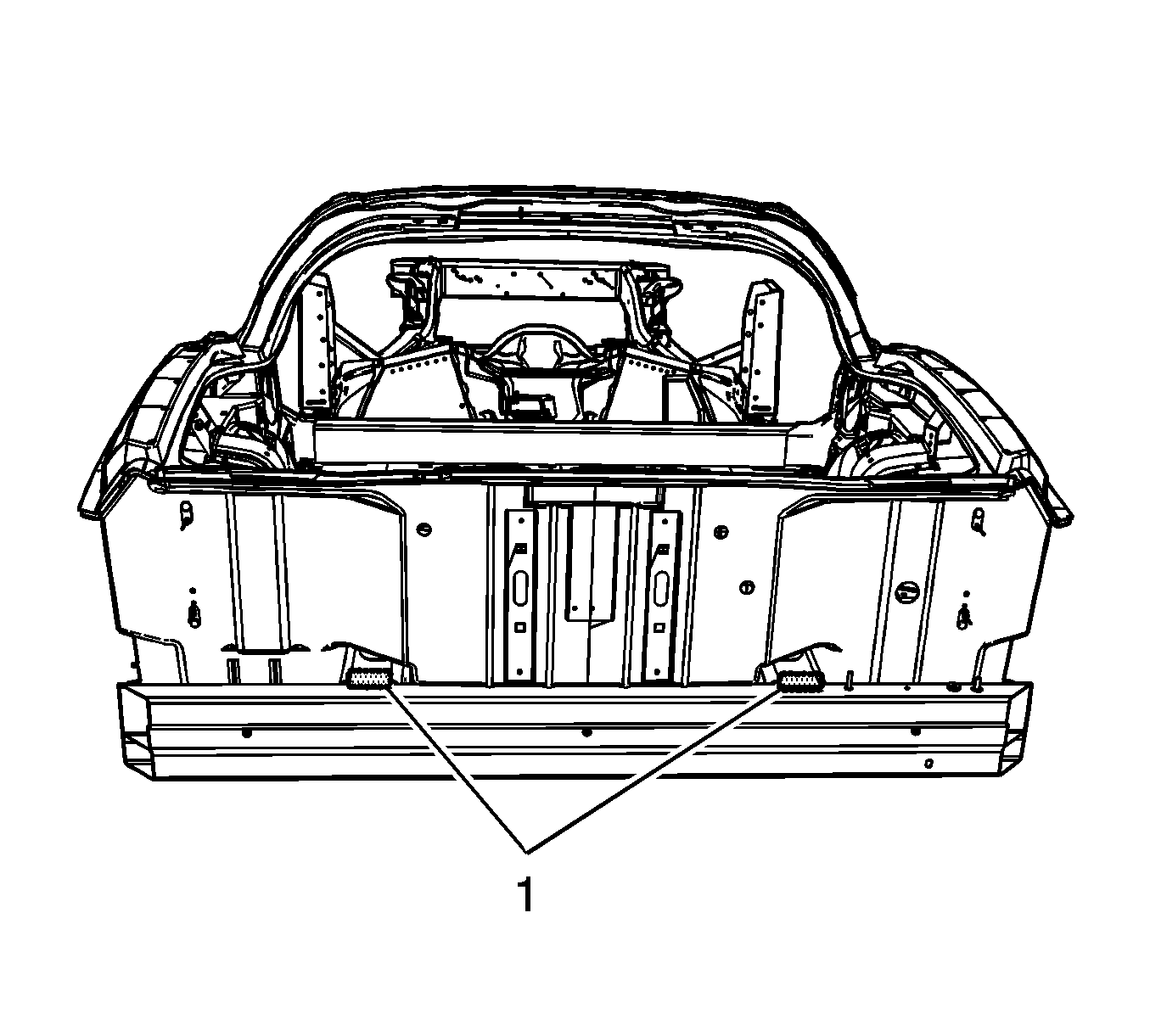
- Using a P-MIG welder, weld (1) the bumper bar to the top of the rear frame rails duplicating the factory welds.
- Using a P-MIG welder, weld (1) the bumper bar to the bottom of the rear frame rails duplicating the factory welds.
- Using a P-MIG welder, weld (1) the bumper bar to the outer and inner of the rear frame rails duplicating the factory welds.
- Clean and prepare all bonding mating surfaces according to adhesive manufacturer's recommendations.
- Apply a consistent bead of structural adhesive to the battery tray to bond to the rear compartment panel. Refer to Sheet Molded Compound (SMC) Panel Bonding .
- install the battery tray (1).
- Clamp or mechanically fasten the battery tray into place as necessary.
- Using a P-MIG welder, weld (1) the battery tray to the bottom of the bumper bar.
- Using a P-MIG welder, weld (1) the outer edge of the battery tray to the bumper bar.
- Using a P-MIG welder, weld (1) the battery tray to the battery tray bracket.
- Clean and prepare all bonding mating surfaces according to adhesive manufacturer's recommendations.
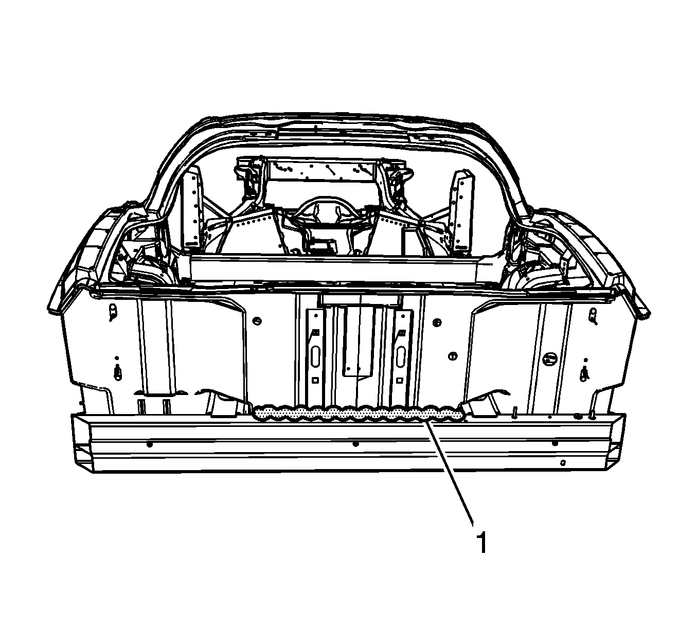
- Apply a consistent bead of structural adhesive to the top impact bar to bond to the rear compartment panel. Refer to Sheet Molded Compound (SMC) Panel Bonding .
- Apply the sealers and anti-corrosion materials to the repair area. Refer to Anti-Corrosion Treatment and Repair .
- Paint the repair area. Refer to Basecoat/Clearcoat Paint Systems .
- Install all related panels and components.
- Connect the negative battery cable. Refer to Battery Negative Cable Disconnection and Connection .
- Enable the SIR system. Refer to SIR Disabling and Enabling .
Important: Due to welding accessibility, it may be necessary to weld the triangle brackets (1) to the bumper bar prior to installation of the bumper bar.
Important: Use a stainless steel brush to remove the oxide layer prior to welding.
Important: Recommended wire alloy is 5356 and wire size is .035. The shielding gas is 100 percent Argon.
A 2 minute cooling down period is recommended for every 2 minutes or 100 mm (4 in) of welding.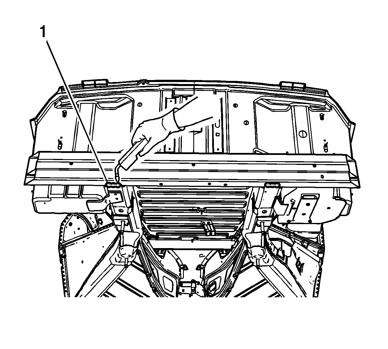
Important: DO NOT top coat the bonding surface of the battery tray. Use primer only on bonding surfaces. Refer to adhesive manufacturer's recommendations.
Important: Due to welding accessibility, it may be necessary to change the weld location of the battery tray to the rear bumper bar.
Important: DO NOT top coat the bonding surface of the rear bar. Use primer only on bonding surfaces. Refer to adhesive manufacturer's recommendations.
