For 1990-2009 cars only
Removal Procedure
- Disable the SIR system. Refer to the following procedures:
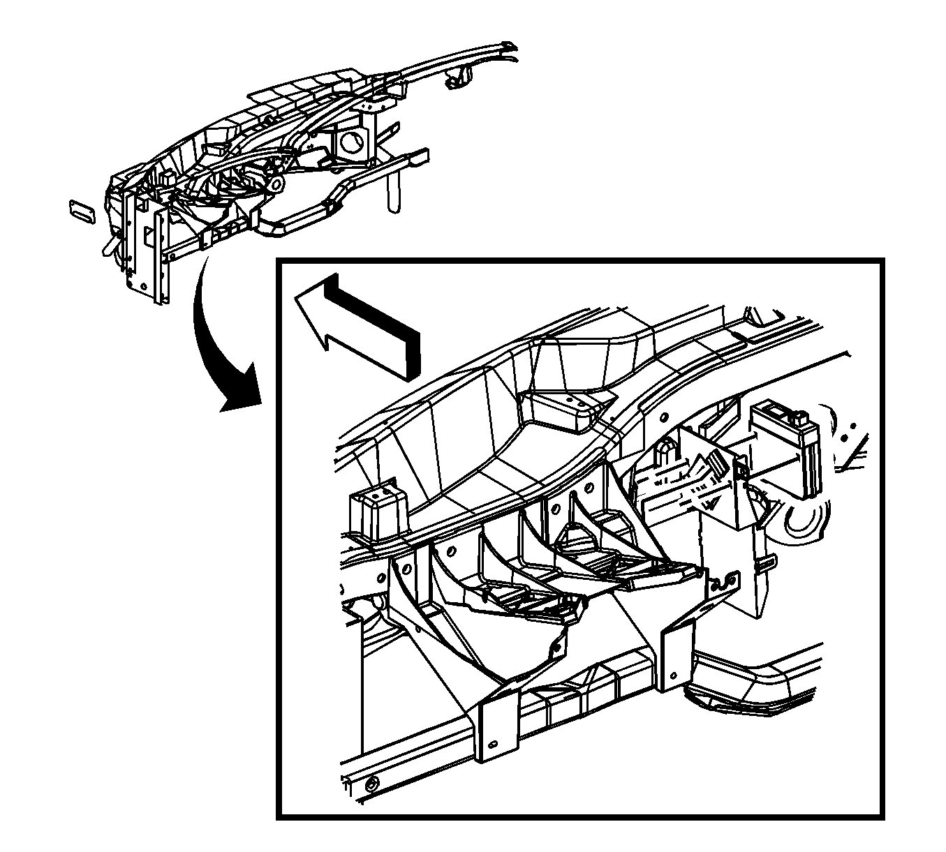
- Remove the I/P Assembly. Refer to Instrument Panel Assembly Replacement in Instrument Panel, Gages, and Console.
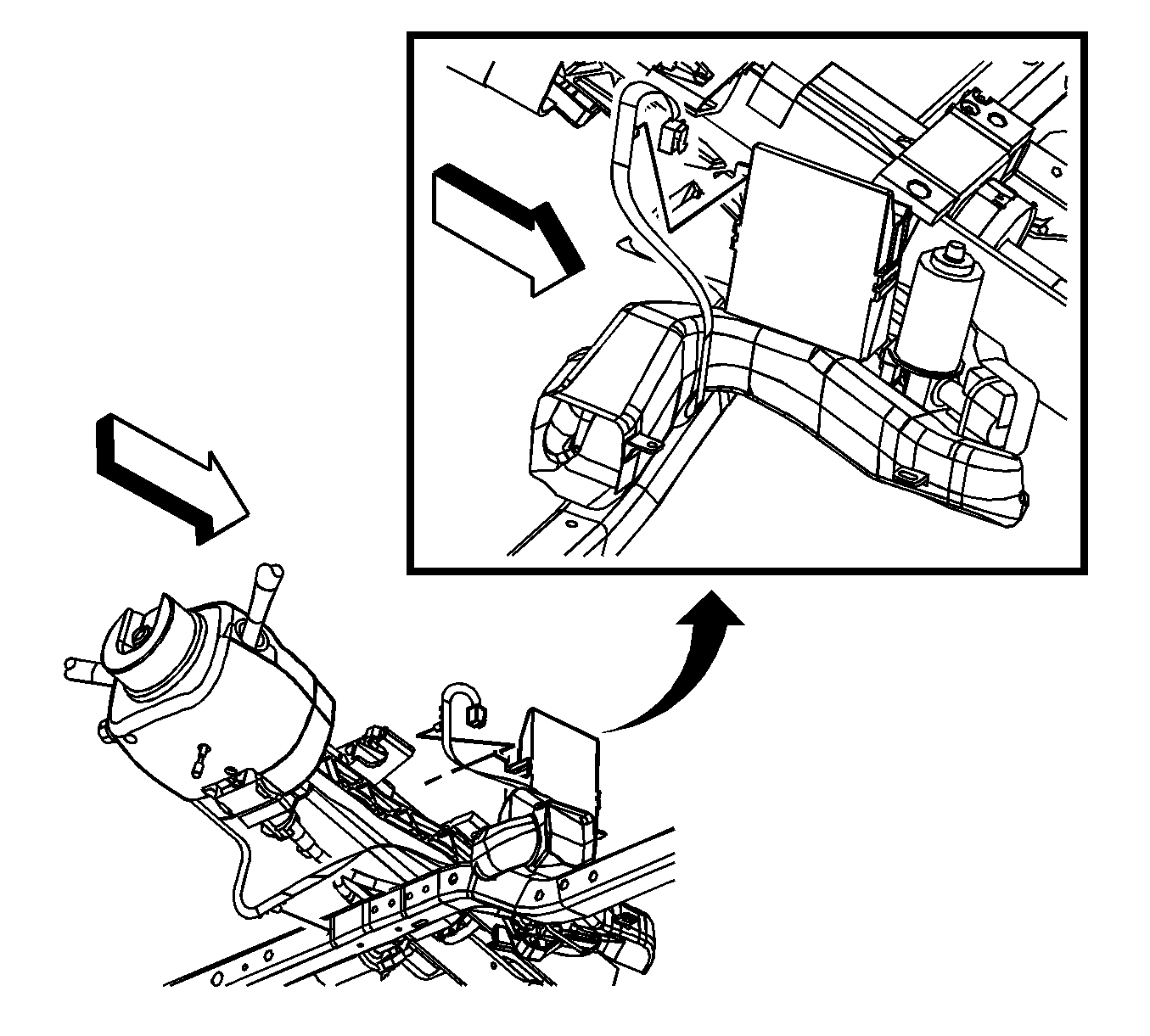
- Disconnect the electrical connectors at the lock module.
- Remove the lock module by pulling the module up to release the retaining clips and sliding the module upward.
Caution: Refer to SIR Caution in the Preface section.

Notice: Avoid damaging the steering column electronic lock harness by gently removing the plugs installed in the I/P beam. Do NOT twist, pull, bend, cut, or incorrectly route the harness. Damage to the harness will require replacement of the entire electronic lock.

Installation Procedure
- Install the control module to the retaining bracket on the steering column.
- Connect the electrical connector to the lock module.
- Install the I/P Assembly. Refer to Instrument Panel Assembly Replacement in Instrument Panel, Gages, and Console.
- Enable the SIR system. Refer to the following procedures:
- Program the lock control module. Refer to Control Module References in Computer/Integrating Systems.


