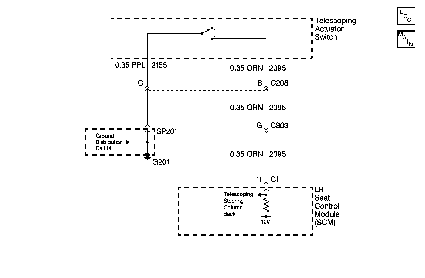
Circuit Description
The telescoping steering column switch circuit provides an input to the LH Seat Control Module (SCM) when the switch is held closed in the in or out position. The SCM monitors a 12 volt signal applied to the steering column switch (circuit 2095). When the steering column switch is closed in the out position, the column out 12 volt signal is grounded and pulled low within the SCM indicating a column out request.
Conditions for Setting the DTC
The steering column out switch input, to the SCM, is active for more than 20 seconds.
Action Taken When the DTC Sets
| • | Stores a history DTC B2857 in the SCM memory. |
| • | This DTC can only be set as a history code even if the malfunction is current. |
| • | No driver warning message will be displayed for this DTC. |
| • | The operation/function of the steering column out switch is disabled. |
Conditions for Clearing the DTC
| • | The steering column out switch input, to the SCM, is inactive for more than 20 seconds. |
| • | Using a scan tool. |
Diagnostic Aids
| • | The following conditions may cause an intermittent malfunction. |
| - | There is an intermittent short to ground in circuit 2095. |
| - | The steering column out switch is shorted to ground internally or is sticking. |
| - | The steering column out switch was closed for longer than 20 seconds. |
| • | If circuit 2095 is shorted to ground or the steering column out switch is stuck closed, the steering column will remain in the full out position at all times. |
| • | Using a scan tool, select scan tool inputs and monitor steering column out switch status. If the scan tool displays ACTIVE, disconnect the steering column out switch. If the display changes to INACTIVE, replace the switch. If the display remains ACTIVE check circuit 2095 for a short to ground. |
| • | If the DTC does not reset outer the code is cleared, then the problem may be intermittent. Perform the tests shown while moving related wiring and connectors. This can often cause the malfunction to occur. Refer to Intermittents and Poor Connections Diagnosis in Wiring Systems. |
| • | Activate the steering column out switch numerous times while monitoring the status on the scan tool to see if it sticks intermittently. |
Test Description
The numbers below refer to the step numbers on the diagnostic table:
-
This test determines the status of the column out switch using a scan tool. The scan tool will display the column out switch status as ACTIVE (button pressed) and INACTIVE (button released).
-
This test checks if the column out switch is shorted to ground or stuck. If the column out switch status changes from ACTIVE to INACTIVE when the column out switch is disconnected, then the switch assembly must be replaced.
Step | Action | Value(s) | Yes | No |
|---|---|---|---|---|
1 | Were you sent here from the Power Seat Diagnostic System Check? | -- | Go to Power Seats System Check | |
2 | Using a scan tool, select SCM input display and monitor the column out switch status. Does the scan tool display column out switch status as ACTIVE? | -- | ||
3 |
Does the scan tool display column out switch status as ACTIVE? | -- | ||
4 | Check for a short to ground in CKT 2095. Was a problem found and repaired? | -- | ||
5 | Replace the telescoping column switch assembly. Refer to Telescope Actuator Switch Replacement - On Vehicle . Is the replacement complete? | -- | -- | |
6 | Replace the SCM. Refer to Memory Seat Control Module Replacement . Is the replacement complete? | -- | -- | |
7 | Check the column out switch circuit for an intermittent malfunction. Refer to Diagnostic Aids. Was a problem found and repaired? | -- | ||
8 |
Does DTC B2857 set as history? | -- | System OK | |
9 |
Is the repair complete? | -- | Go to Power Seats System Check | -- |
