Removal Procedure
- Remove the console. Refer to
Console Replacement
.
- Remove the I/P accessory trim plate. Refer to
Instrument Panel Accessory Trim Plate Replacement
.
- Remove the driver knee bolster trim panel. Refer to
Driver Knee Bolster Panel Replacement
.
- Remove the instrument panel compartment. Refer to
Instrument Panel Compartment Replacement
.
- Remove the windshield defroster grille. Refer to
Defroster Grille Replacement
.
- Insert the DRL and sunload sensors, if equipped, into the nearest
openings in the windshield defroster duct.
Moving the sensors into the defroster duct provides additional clearance
to remove the trim pad.
- Remove the windshield side garnish moldings. Refer to
Windshield Side Garnish Molding Replacement
in Stationary Windows.
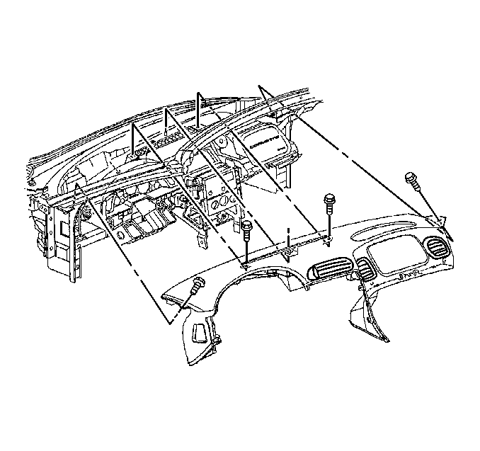
- Remove the screws retaining the upper trim pad to the defroster
duct.
- Remove the screws retaining the upper trim pad to the LH and RH
hinge pillars.
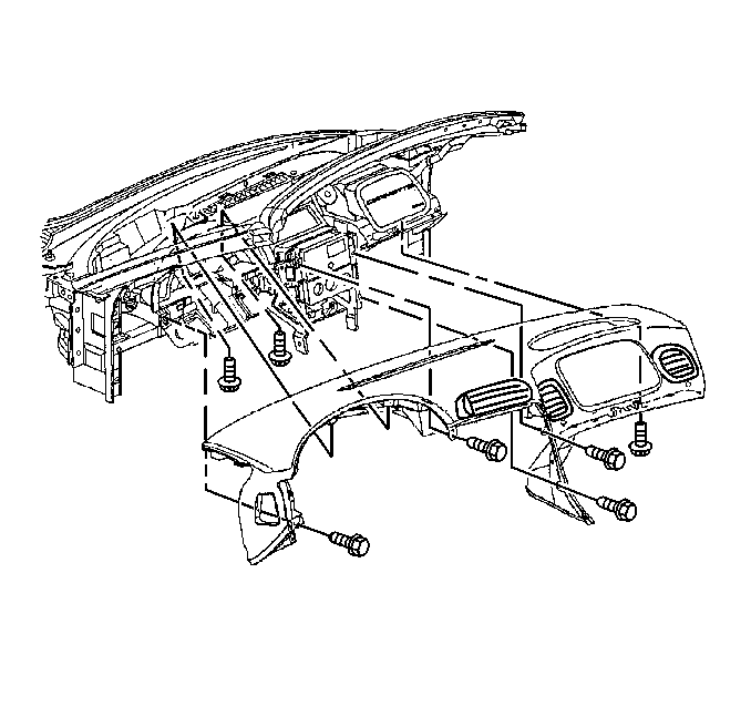
- Remove the screws retaining the I/P cluster bezel to the upper trim pad.
- Remove the screws retaining the upper trim pad to the driver knee
bolster outer bracket and the center support bracket.
- Remove the screw retaining the upper trim pad to the passenger
SIR bracket.
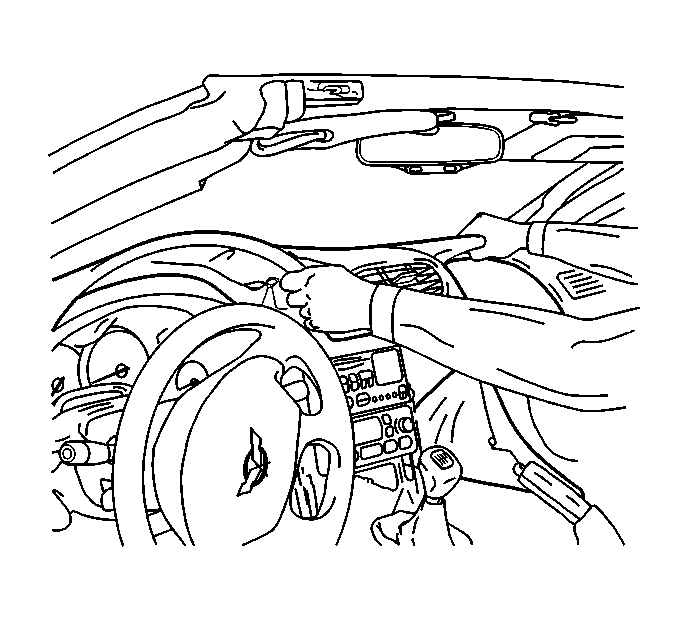
- Tilt the steering wheel to the lowest position.
- Lift the rearward edge of the upper trim pad approximately 2 inches
to provide clearance for the air distribution duct located on the underside
of the trim pad.
- SLOWLY pull the upper trim pad away from the windshield while
guiding the tabs on the LH and RH side of the trim pad past the hinge pillars.
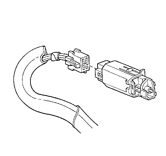
- Disconnect the hazard warning switch electrical connector.
- Remove the upper trim pad from the vehicle.
Installation Procedure
- Connect the hazard warning switch electrical connector.
- Install the I/P upper trim pad into position.
| 2.1. | Tilt the forward edge of the trim pad down slightly. |
| 2.2. | SLOWLY begin to move the trim pad into position while guiding
the tabs on the LH and RH side of the trim pad past the hinge pillars. |
| 2.3. | Locate the trim pad by guiding the alignment notch on the underside
of the pad onto the alignment pin on the dash panel. |
| 2.4. | Lower the rearward edge of the pad into place. |
- Remove the DRL and sunload sensors, if equipped, from the openings
in the windshield defroster duct and position above the trim pad.
- Install the screws retaining the upper trim pad to the windshield defroster
duct.
Tighten
Tighten the I/P upper trim pad to windshield defroster duct screws to
1.9 N·m (17 lb in).
Notice: Use the correct fastener in the correct location. Replacement fasteners
must be the correct part number for that application. Fasteners requiring
replacement or fasteners requiring the use of thread locking compound or sealant
are identified in the service procedure. Do not use paints, lubricants, or
corrosion inhibitors on fasteners or fastener joint surfaces unless specified.
These coatings affect fastener torque and joint clamping force and may damage
the fastener. Use the correct tightening sequence and specifications when
installing fasteners in order to avoid damage to parts and systems.
- Install the screws retaining the upper trim pad to the LH and
RH hinge pillars.
Tighten
Tighten the I/P upper trim pad to LH and RH hinge pillar screws
to 2.5 N·m (22 lb in).
- Install the screws retaining the upper trim pad to the driver knee bolster
outer bracket, the center support bracket and the passenger SIR bracket.
Tighten
| • | Tighten the I/P upper trim pad to driver knee bolster outer bracket
screw to 1.9 N·m (17 lb in). |
| • | Tighten the I/P upper trim pad to I/P center support bracket screws
to 1.9 N·m (17 lb in). |
| • | Tighten the I/P upper trim pad to passenger SIR bracket screw
to 1.9 N·m (17 lb in). |
- Install the screws retaining the I/P cluster bezel to the upper
trim pad.
Tighten
Tighten the I/P cluster bezel to I/P upper trim pad screws to 1.3 N·m
(12 lb in).
- Install the windshield side garnish moldings. Refer to
Windshield Side Garnish Molding Replacement
in Stationary Windows.
- Install the windshield defroster grille. Refer to
Defroster Grille Replacement
.
- Install the instrument panel compartment. Refer to
Instrument Panel Compartment Replacement
.
- Install the driver knee bolster trim panel. Refer to
Driver Knee Bolster Panel Replacement
.
- Install the I/P accessory trim plate. Refer to
Instrument Panel Accessory Trim Plate Replacement
.
- Install the console. Refer to
Console Replacement
.
