Refer to
Fuel Injectors
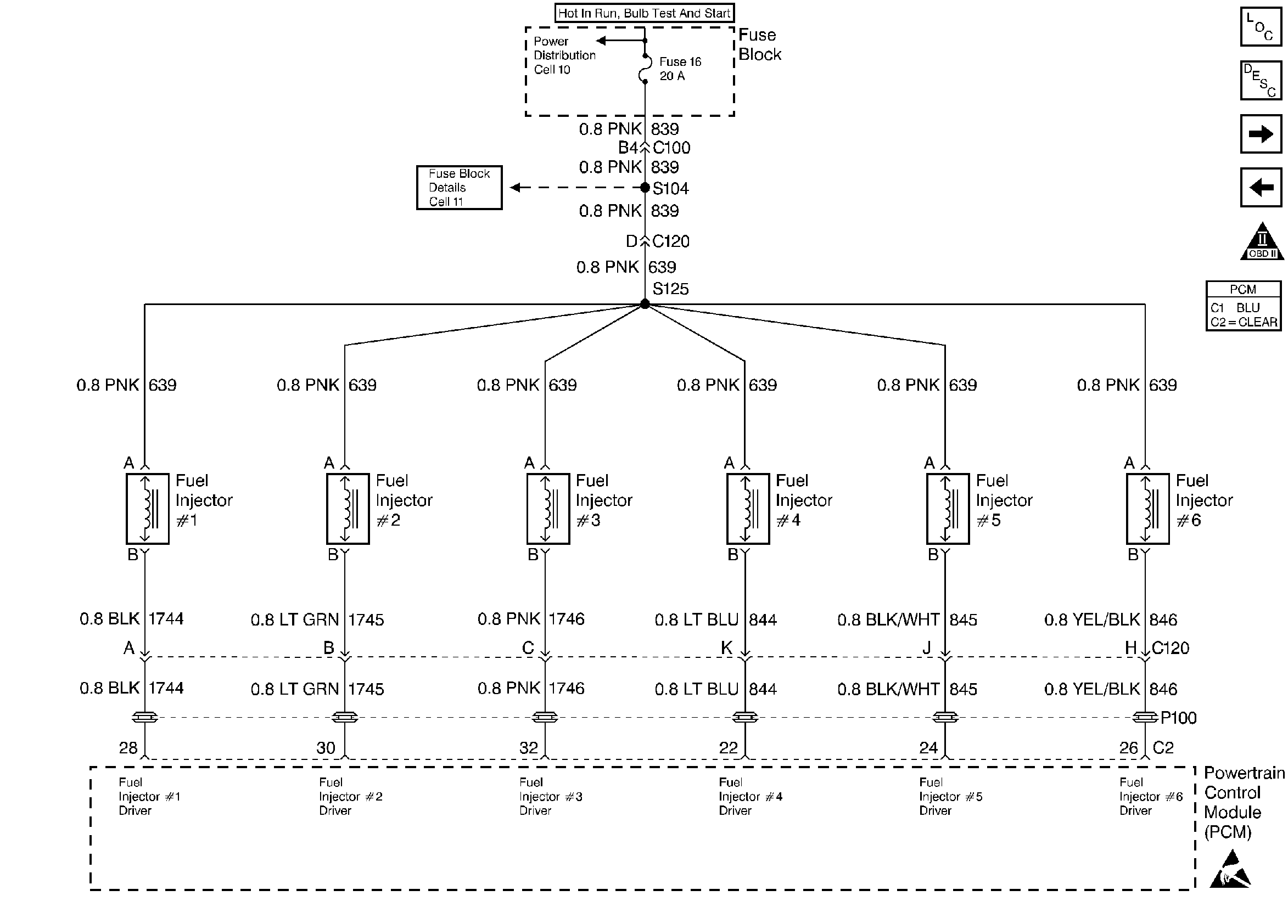
Circuit Description
The PCM controls the fuel injector driver circuit using a General FET Driver (GFD). The GFD has the ability to detect an electrical fault on any of the injector ignition feed or driver circuits. If an electrical fault is detected, the GFD signals the PCM to set DTC P1200.
Conditions for Setting the DTC
| • | An incorrect voltage level is being detected on an injector driver circuit. |
| • | Above condition for over 5 seconds. |
Action Taken When the DTC Sets
| • | The PCM will illuminate the malfunction indicator lamp (MIL) during the second consecutive trip in which the diagnostic test has been run and failed. |
| • | The PCM will store conditions which were present when the DTC set as Freeze Frame and Failure Records data. |
Conditions for Clearing the MIL/DTC
| • | The PCM will turn OFF the MIL during the third consecutive trip in which the diagnostic has been run and passed. |
| • | The History DTC will clear after 40 consecutive warm-up cycles have occurred without a malfunction. |
| • | The DTC can be cleared by using the scan tool. |
Diagnostic Aids
The misfire history counters may be useful in determining which injector circuit is faulty. If DTC P0300 was set, look at the Misfire Hist # display for each cylinder. The largest value stored in the misfire history counters will indicate the location of the faulty injector circuit or injector.
Check for the following conditions:
| • | Poor connection at PCM. Inspect harness connectors for backed out terminals, improper mating, broken locks, improperly formed or damaged terminals, and poor terminal to wire connection. |
| • | Damaged harness. Inspect the wiring harness for damage. If the harness appears to be OK, observe the display on the scan tool while moving connectors and wiring harnesses related to the sensor. A change in the display will indicate the location of the fault. |
Reviewing the Fail Records vehicle mileage since the diagnostic test last failed may help determine how often the condition that caused the DTC to be set occurs. This may assist in diagnosing the condition.
Test Description
Number(s) below refer to the step number(s) on the Diagnostic Chart.
Step | Action | Value(s) | Yes | No |
|---|---|---|---|---|
1 | Was the Powertrain On-Board Diagnostic System Check performed? | -- | Go to POWERTRAIN ON-BOARD DIAGNOSTIC System Check | |
2 | Engine idling, monitor SPECIFIC DTC info for DTC P1200 on the scan tool. Does the scan tool indicate DTC P1200 failed this ignition? | -- | ||
3 |
Does the scan tool indicate DTC P1200 failed this ignition? | -- | Go to Diagnostic Aids | |
Did all of the LEDs flash for cylinders 1-6? | -- | |||
5 | Perform the Injector Coil Test. Is Action Complete? | -- | -- | |
6 | Did some of the of the LEDs flash for cylinders 1-6? | -- | ||
7 |
Was a problem found? | -- | ||
8 | Check the injector driver circuit(s) with the LEDs that did not flash for opens, shorts to voltage and shorts to grounds. If a problem is found, repair as necessary. Refer to Repair procedures in Electrical Diagnosis Section 8A. Was problem found? | -- | ||
9 |
Is action complete? | -- | -- | |
10 |
Was a problem found? | -- | ||
11 | Replace the PCM. Important: The replacement PCM must be programmed. Refer to PCM Replacement/Programming. Is action complete? | -- | -- | |
12 |
Does the scan tool indicate DTC P1200 failed this ign? | -- | Repair complete. If a driveability symptom still exists, refer to Symptoms |
