MANUAL UPDATE-FRT.DOOR WINDOW REGULATOR MOTOR

Model and Year: 1987-89 BERETTA, CORSICA WITH POWER WINDOWS
This bulletin describes a revised procedure to replace electric window lift motors from front window regulator mechanisms on 1987-89 Corsica/Beretta styles in the following section of these Service manuals.
1987-88 Service Manual - Section 10, Page 5L-18
1989 Service Manual - Section 10, Page 10-5-20
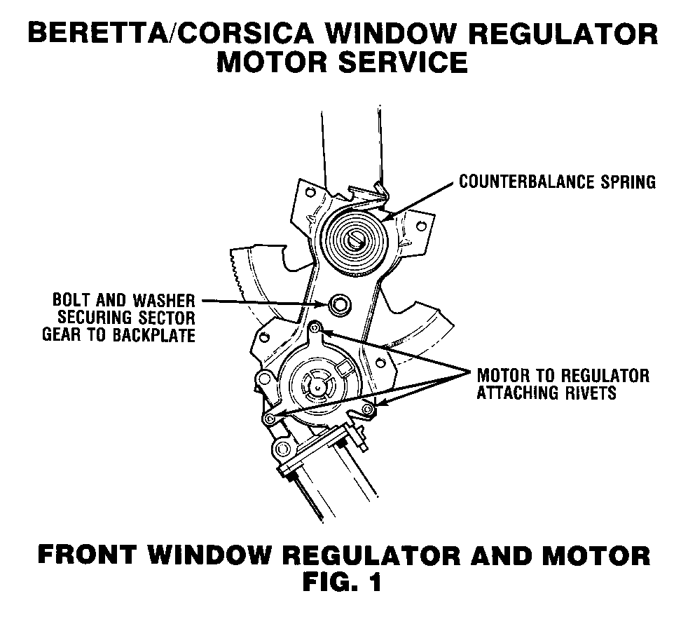
1. Remove regulator and motor from door and carefully inspect the assembly for presence of counterbalance spring. (Some regulators mostly Coupe styles, use the counterbalance springs while most Sedan styles do not) see Figure 1.
IMPORTANT: IF THE REGULATOR DOES HAVE A COUNTERBLANCE SPRING, CONTINUE TO FOLLOW THIS PROCEDURE. IF COUNTERBALANCE SPRINGS ARE NOT PRESENT, PROCEED TO STEP 3.
CAUTION:
STEP 2 MUST BE PERFORMED WHEN REGULATOR IS REMOVED FROM DOOR. THE REGULATOR LIFT ARM IS UNDER TENSION FROM THE COUNTERBALANCE SPRING AND CAN CAUSE PERSONAL INJURY IF THE MOTOR IS REMOVED WITHOUT LOCKING THE SECTOR GEAR IN POSITION.
2. Drill a hole through the regulator sector gear and backplate (See Figure 1) and install a bolt and nut to lock sector gear in position. Do not drill hole closer than 13 mm (1/2") to edge of sector gear or backplate.
3. Using a 1/4" drill bit, drill out the ends of all 3 motor to regulator attaching rivets from the motor side of the assembly.
4. Remove motor from regulator and the remaining portions of the rivets.
IMPORTANT: Depending on the position of the regulator, it may be necessary to remove portions of one remaining rivet in a later step.
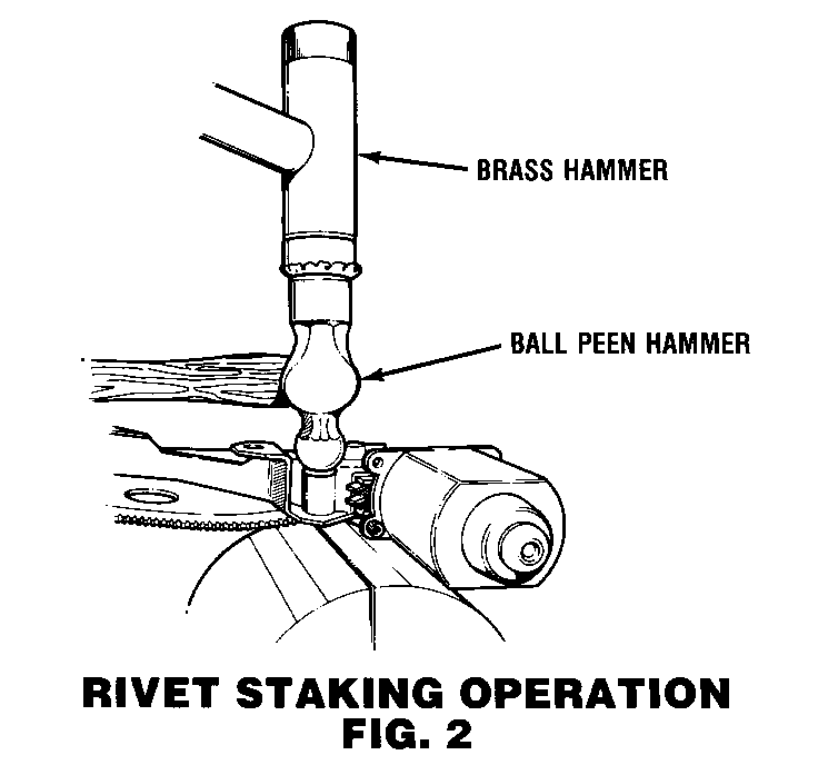
5. Position the new motor to regulator backplate, and with the aid of a helper, install new rivets (P/N 9441949) by collapsing or crushing the end of the rivet with a ball peen type hammer as shown in Figure 2.
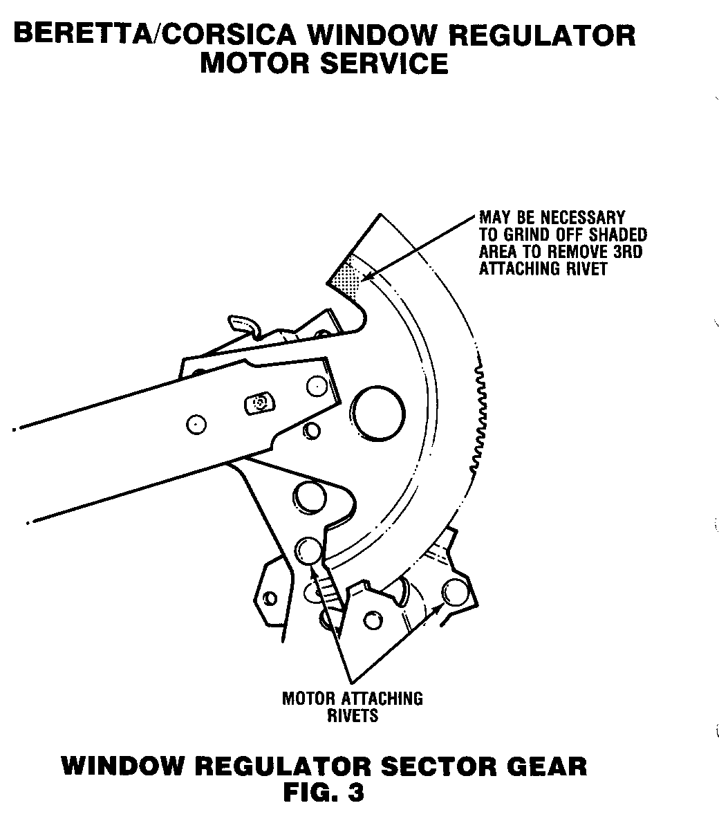
6. Once the motor is secured to the backplate with 2 rivets, remove the bolt securing the sector gear to the backplate and, using an electric power source, rotate the regulator in the desired direction to provide access to the remaining rivet.
IMPORTANT: It may be necessary to grind a portion off of the sector gear to provide space to remove and install the remaining rivet. See Figure 3.
7. Once the remaining rivet can be removed, install new rivet, (P/N 9441949) in the same fashion as step 5 (See Figure 2).
8. Reinstall the regulator and motor assembly into door using 1/4" x 1/2" peel type rivet.


General Motors bulletins are intended for use by professional technicians, not a "do-it-yourselfer". They are written to inform those technicians of conditions that may occur on some vehicles, or to provide information that could assist in the proper service of a vehicle. Properly trained technicians have the equipment, tools, safety instructions and know-how to do a job properly and safely. If a condition is described, do not assume that the bulletin applies to your vehicle, or that your vehicle will have that condition. See a General Motors dealer servicing your brand of General Motors vehicle for information on whether your vehicle may benefit from the information.
