For 1990-2009 cars only
Removal Procedure
Caution: Refer to Brake Fluid Irritant Caution in the Preface section.
Notice: Refer to Brake Fluid Effects on Paint and Electrical Components Notice in the Preface section.
- Remove the master cylinder assembly. Refer to Master Cylinder Replacement .
- Remove the knee bolster trim panel. Refer to Knee Bolster Replacement in Instrument Panel, Gages, and Console
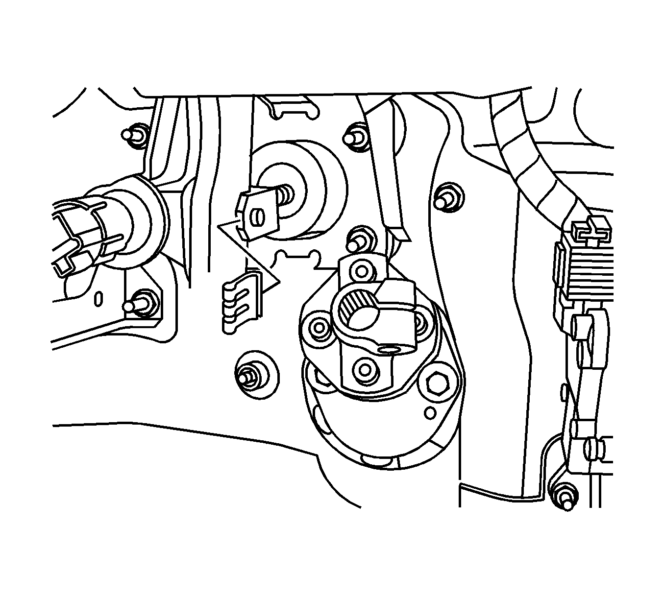
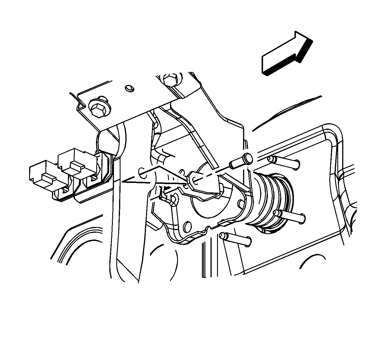
- Remove the retaining clip for the pushrod for the brake booster.
- Remove the clevis pin.
- Remove the pushrod from the brake pedal.
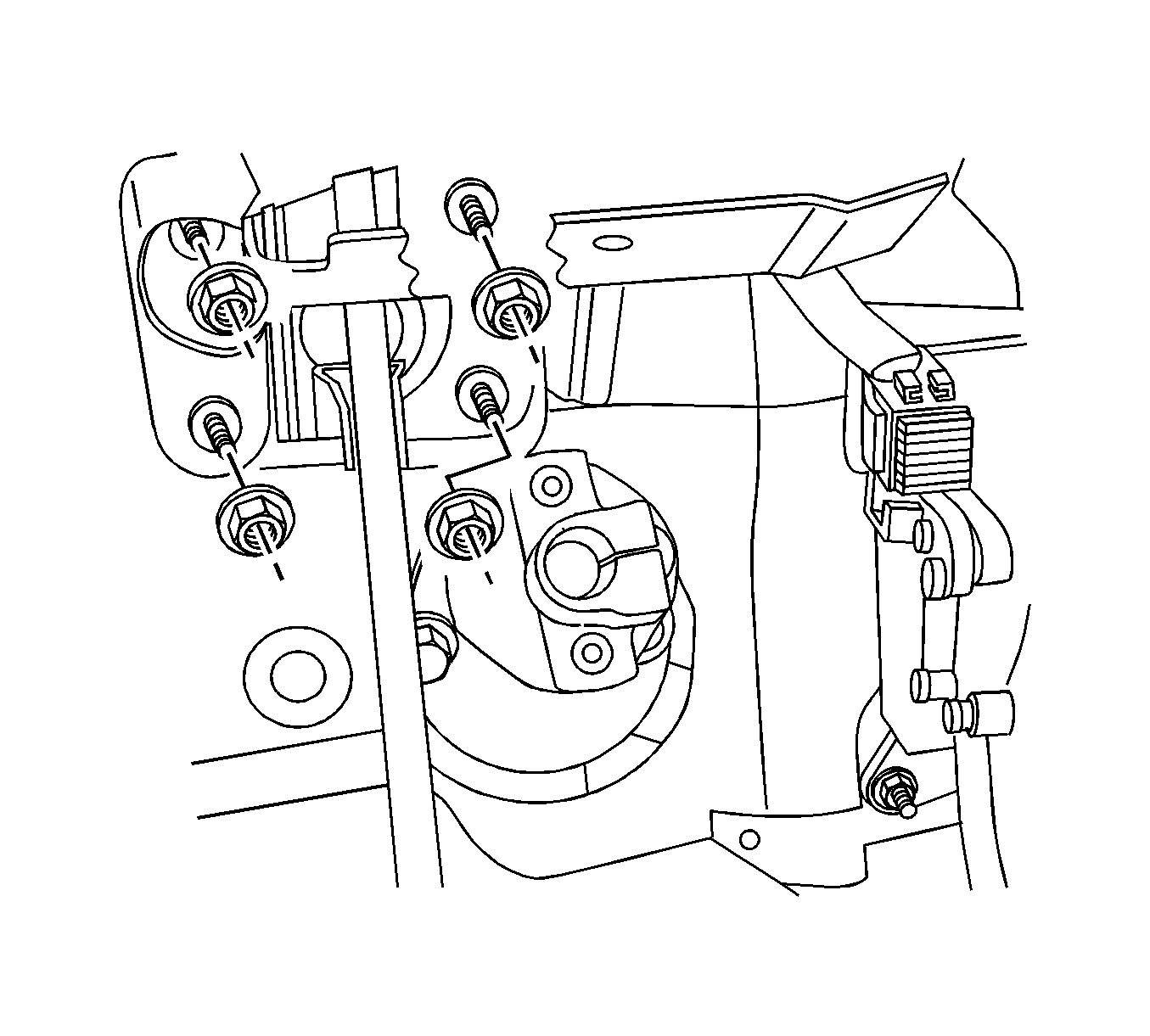
- Remove the mounting nuts for the brake booster.
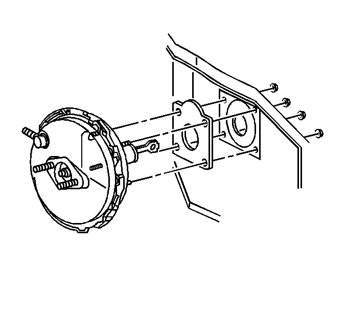
- Remove the brake booster from the vehicle.


Installation Procedure
- Install the brake booster in the bulkhead.
- Install the mounting nuts for the brake booster.
- Install the pushrod on the brake pedal.
- Install the clevis pin.
- Install the retaining clip.
- Adjust the stop lamp switch. Refer to Stop Lamp Switch Adjustment in Lighting Systems.
- Adjust the cruise control release switch. Refer to Cruise Release Switch Adjustment in Cruise Control.
- Install the knee bolster trim panel. Refer to Knee Bolster Replacement in Instrument Panel, Gages, and Console.
- Install the master cylinder assembly. Refer to Master Cylinder Replacement .

Notice: Refer to Fastener Notice in the Preface section.

Tighten
Tighten the brake booster mounting nuts to 20 N·m (15 lb ft).


