GM Service Manual Online
For 1990-2009 cars only
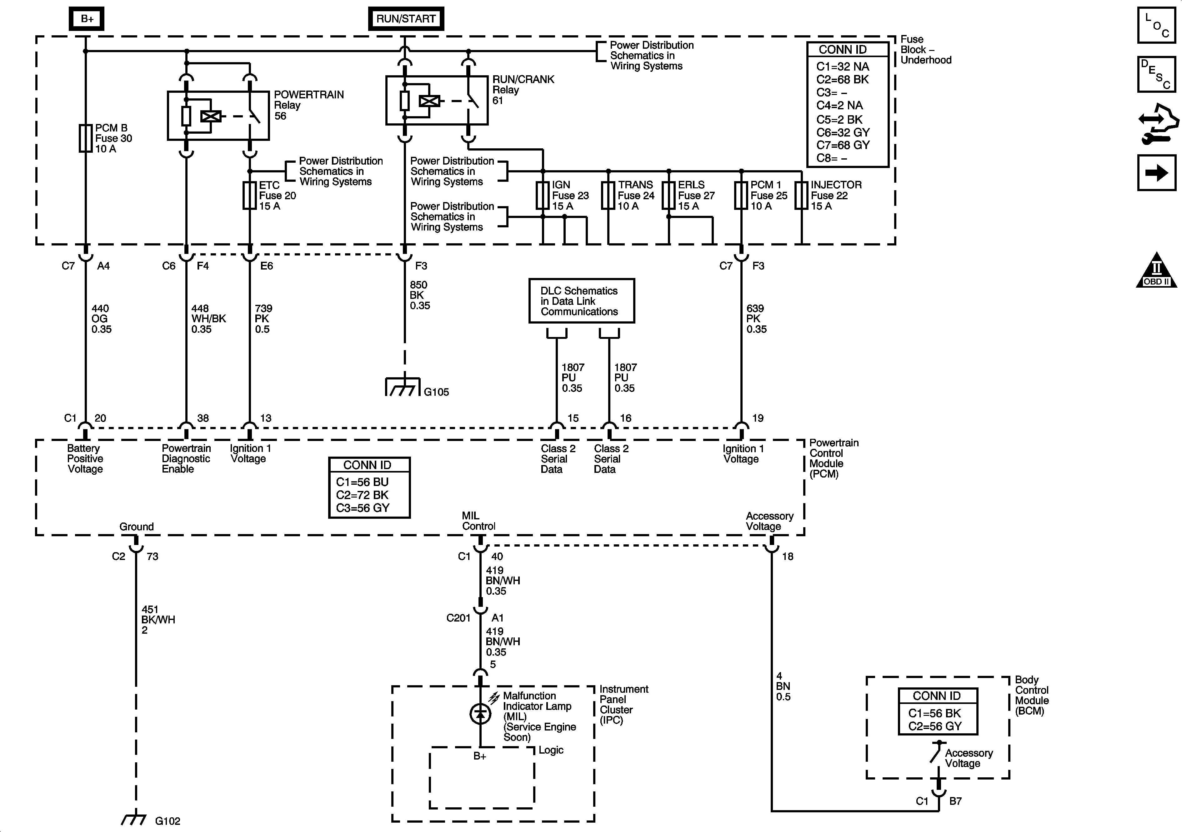
Figure 1:

Module Power, Ground, Serial Data, and MIL

Object Number: 1696931  Size: FS
Master Electrical Component List
Air Intake System Description
Body Control Module (BCM) Programming/RPO Configuration
Engine Data Sensors - 5-Volt and Low Reference
Engine Controls Schematic Icons
B+ Bus - Underhood Fuse Block
Data Link Connector (DLC) Schematics
Splice Pack SP1`05 and G105 - 1 of 2
Ignition Switch and IGN TRANS D Fuse
G100, G104, G102, G103, and G101
Figure 2:

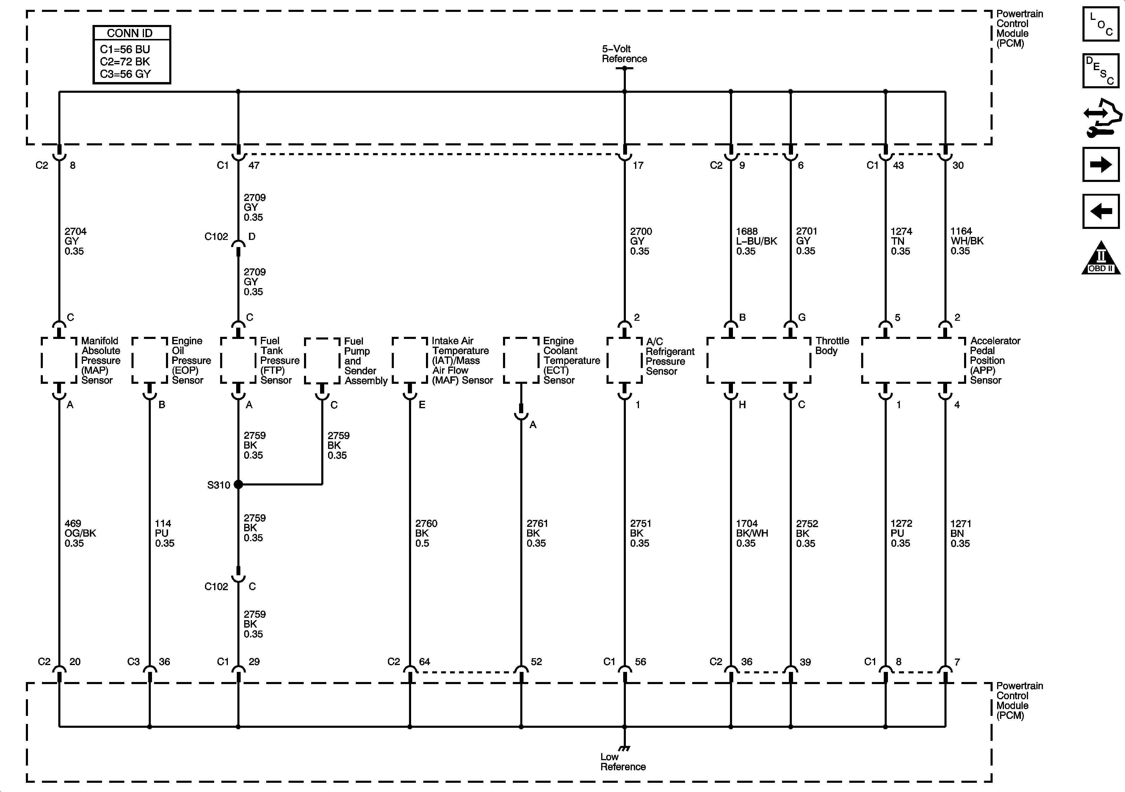
Engine Data Sensors - 5-Volt and Low Reference


Object Number: 1696936  Size: FS
Master Electrical Component List
Air Intake System Description
Body Control Module (BCM) Programming/RPO Configuration
Engine Data Sensors - Pressure, Temperature, and Pedal Position
Module Power, Ground, Serial Data, and MIL
Engine Controls Schematic Icons
Figure 3:

Engine Data Sensors - Electronic Throttle Controls, MAF, Pressure, and Temperature
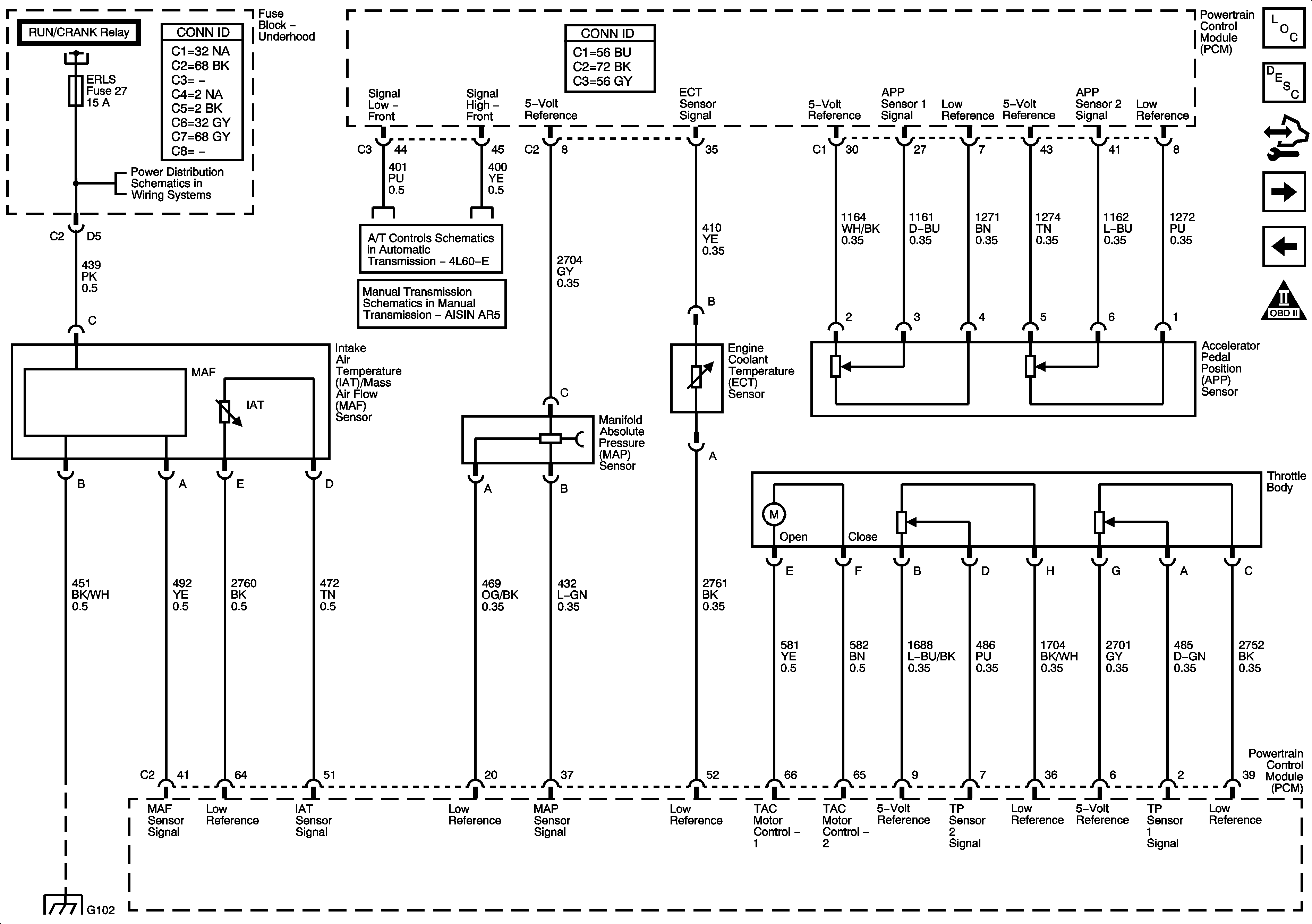

Object Number: 1696937  Size: FS
Master Electrical Component List
Throttle Actuator Control (TAC) System Description
Body Control Module (BCM) Programming/RPO Configuration
Oxygen Sensors
Engine Data Sensors - 5-Volt and Low Reference
Engine Controls Schematic Icons
B+ Bus - Underhood Fuse Block
TCC Brake/Cruise Release Switch and Vehicle Speed Sensor
Manual Transmission Schematics
G100, G104, G102, G103, and G101
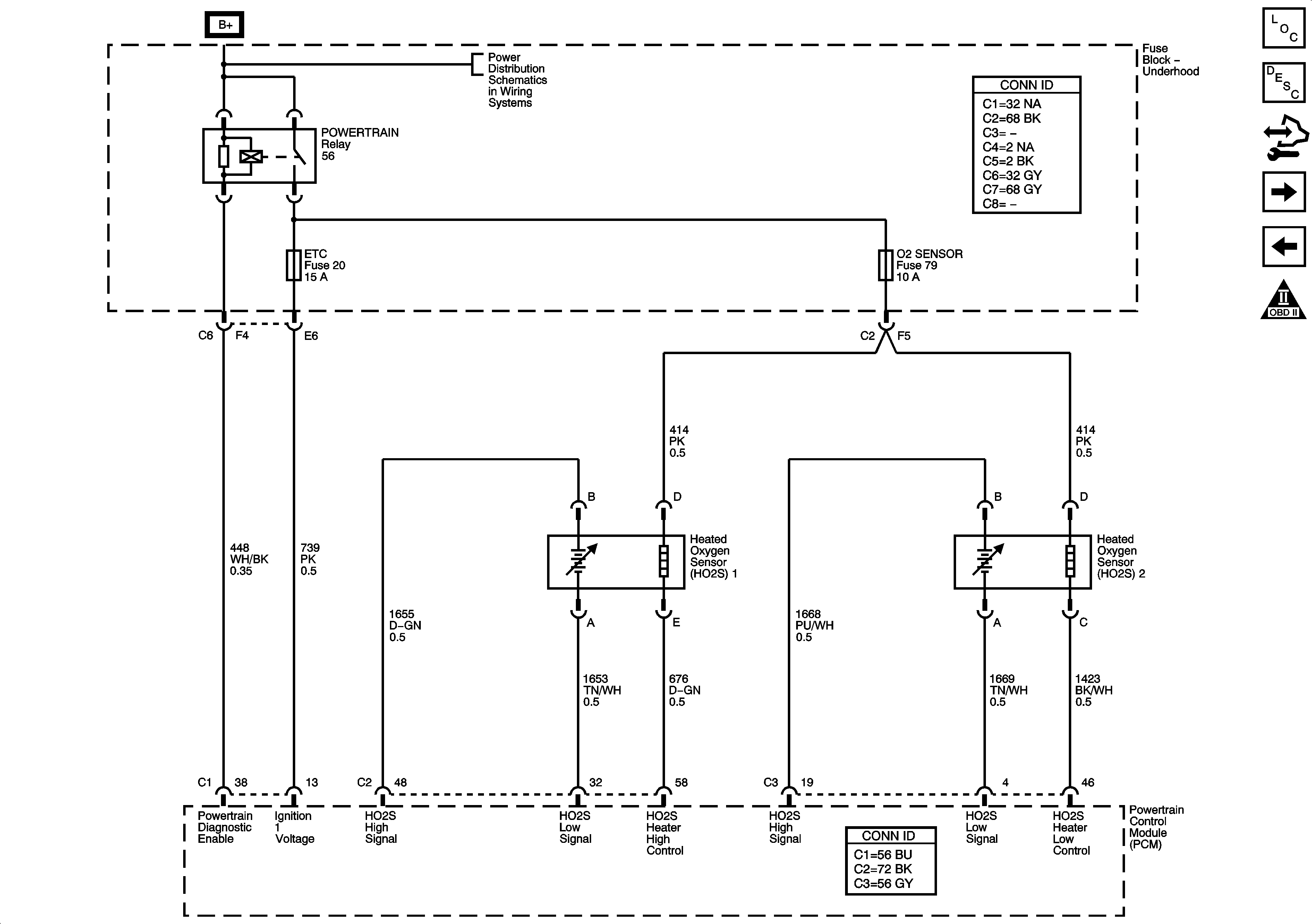
Figure 4:

Engine Data Sensors - Oxygen Sensors


Object Number: 1696941  Size: FS
Master Electrical Component List
Evaporative Emission Control System Description
Body Control Module (BCM) Programming/RPO Configuration
Engine Data Sensors - Injection Timing Controls
Engine Data Sensors - Pressure, Temperature, and Pedal Position
Engine Controls Schematic Icons
B+ Bus - Underhood Fuse Block
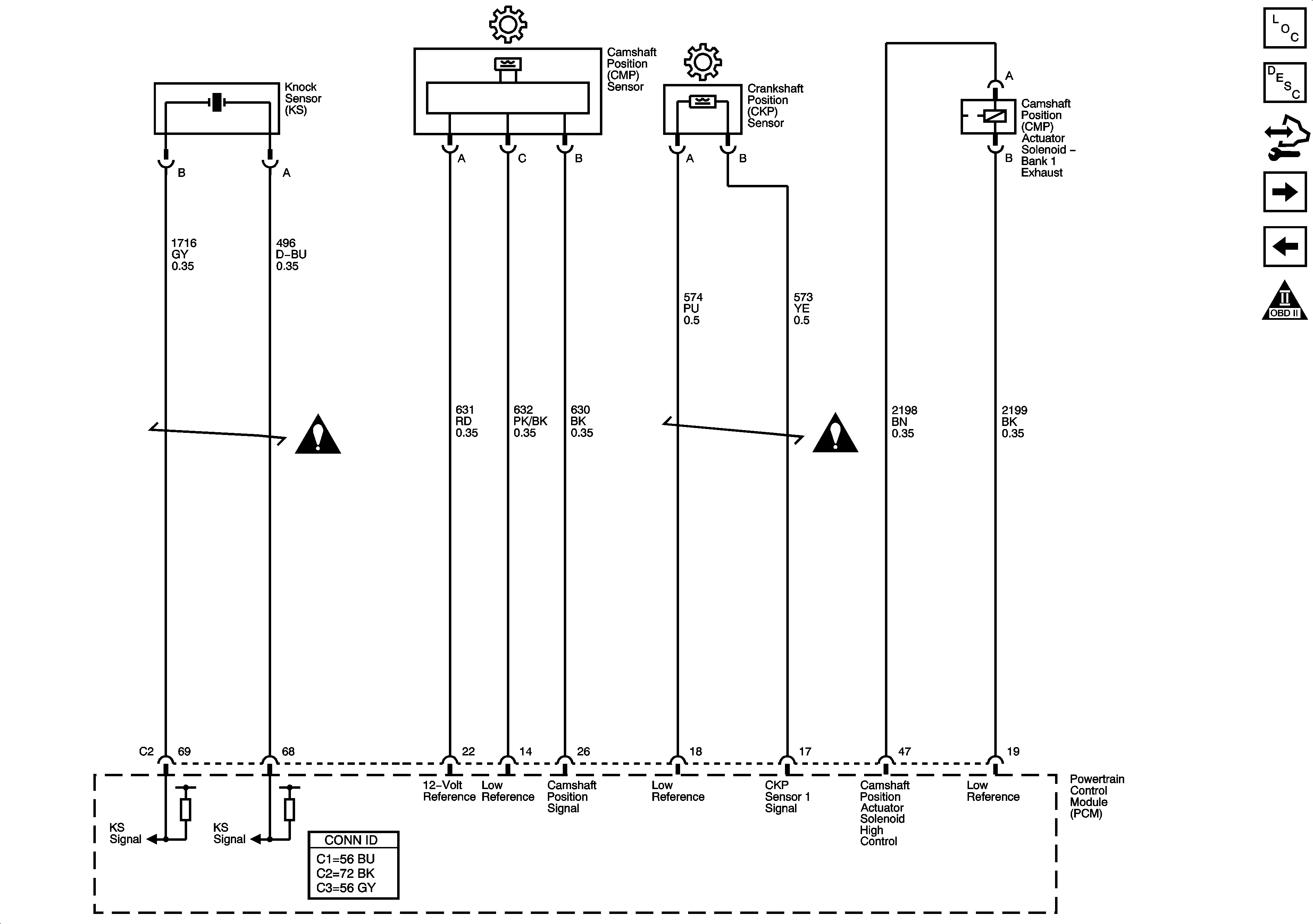
Figure 5:

Ignition Controls - Sensors


Object Number: 1696942  Size: FS
Master Electrical Component List
Camshaft Actuator System Description
Body Control Module (BCM) Programming/RPO Configuration
Ignition COntrols - Ignition Systems
Oxygen Sensors
Engine Controls Schematic Icons
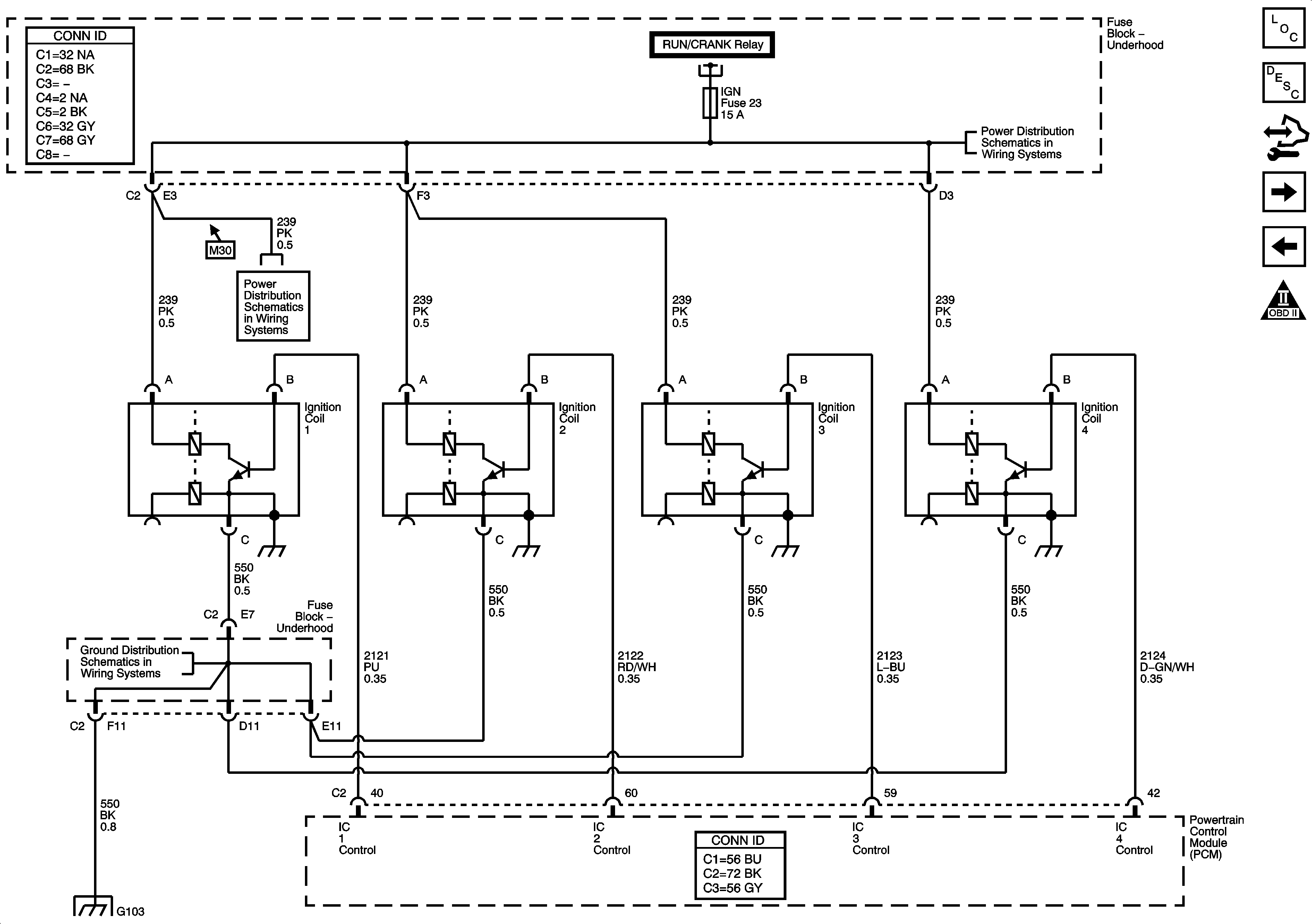
Figure 6:

Ignition Controls - Ignition System


Object Number: 1696947  Size: FS
Master Electrical Component List
Knock Sensor (KS) System Description
Body Control Module (BCM) Programming/RPO Configuration
Fuel Controls - Fuel Pump Controls
Engine Data Sensors - Injection Timing Controls
Engine Controls Schematic Icons
Module Power, Ground, Serial Data, and MIL
RUN/CRANK RELAY BUS - 2 of 3, CRUISE, SIR, and TRANS Fuses
G100, G104, G102, G103, and G101
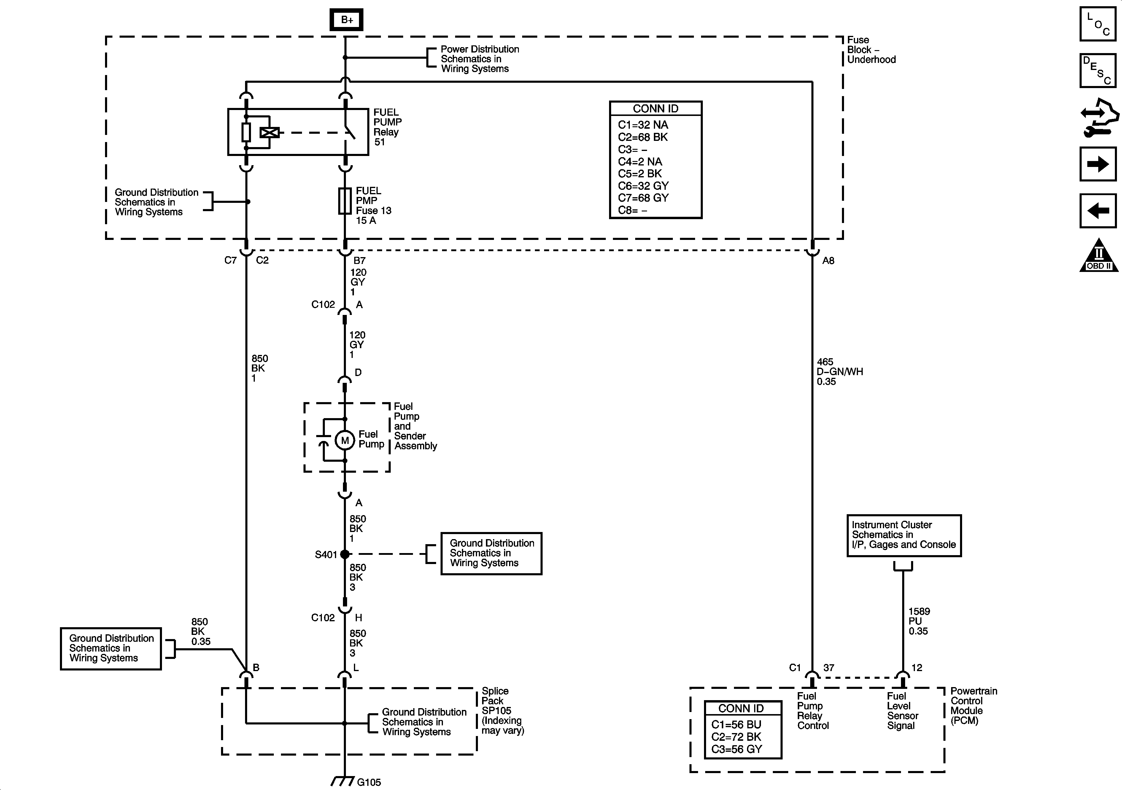
Figure 7:

Fuel Controls - Fuel Pump Controls


Object Number: 1696948  Size: FS
Master Electrical Component List
Fuel System Description
Body Control Module (BCM) Programming/RPO Configuration
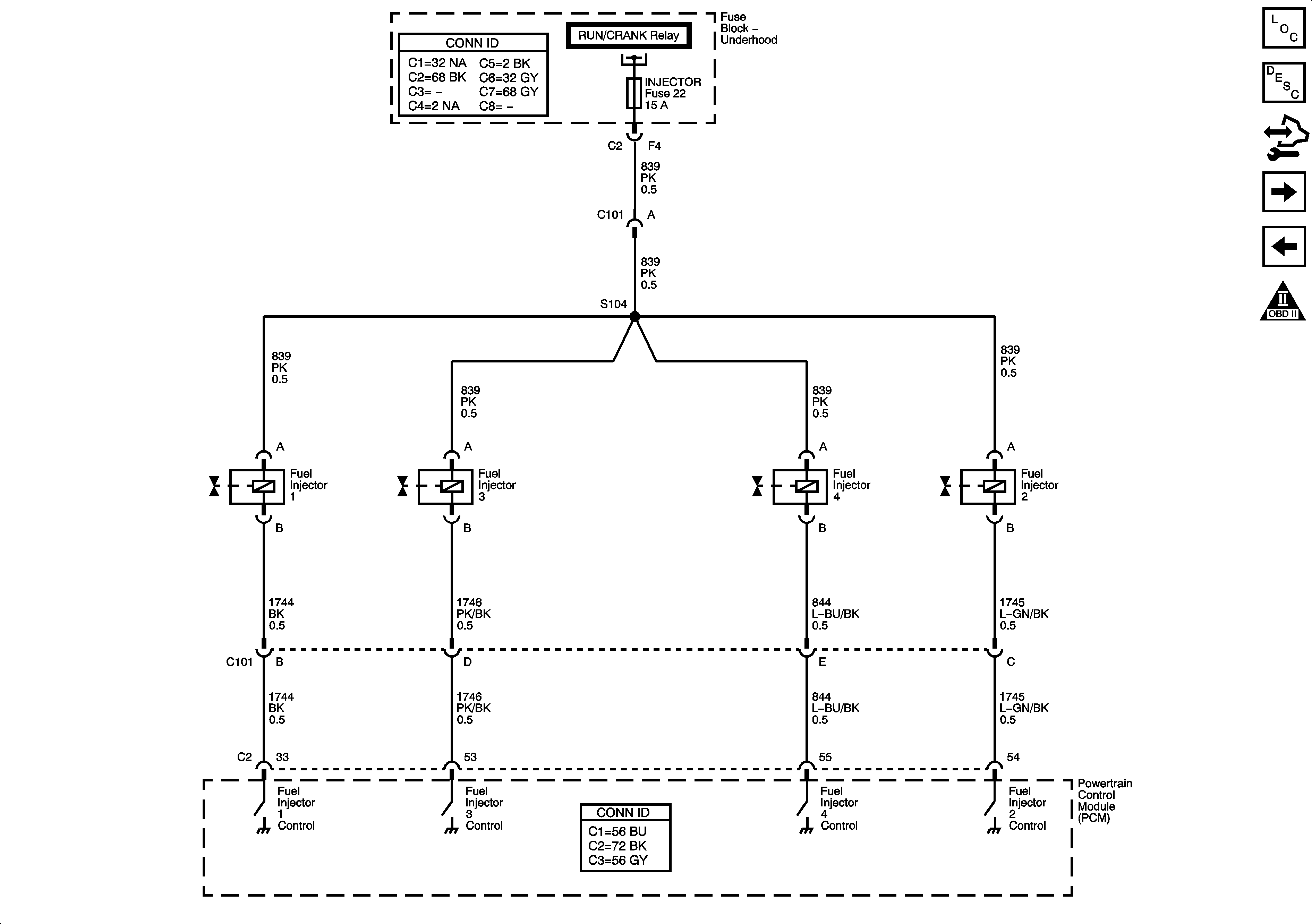
Fuel Controls - Fuel Injectors
Ignition COntrols - Ignition Systems
Engine Controls Schematic Icons
B+ Bus - Underhood Fuse Block
Splice Pack SP1`05 and G105 - 1 of 2
Splice Pack SP1`05 and G105 - 2 of 2
Splice Pack SP1`05 and G105 - 1 of 2
Gages
Figure 8:

Fuel Controls - Fuel Injectors


Object Number: 1696949  Size: FS
Master Electrical Component List
Fuel System Description
Body Control Module (BCM) Programming/RPO Configuration
Fuel Controls - Fuel Pressure Sensor/Regulator
Fuel Controls - Fuel Pump Controls
Engine Controls Schematic Icons
Module Power, Ground, Serial Data, and MIL
Figure 9:

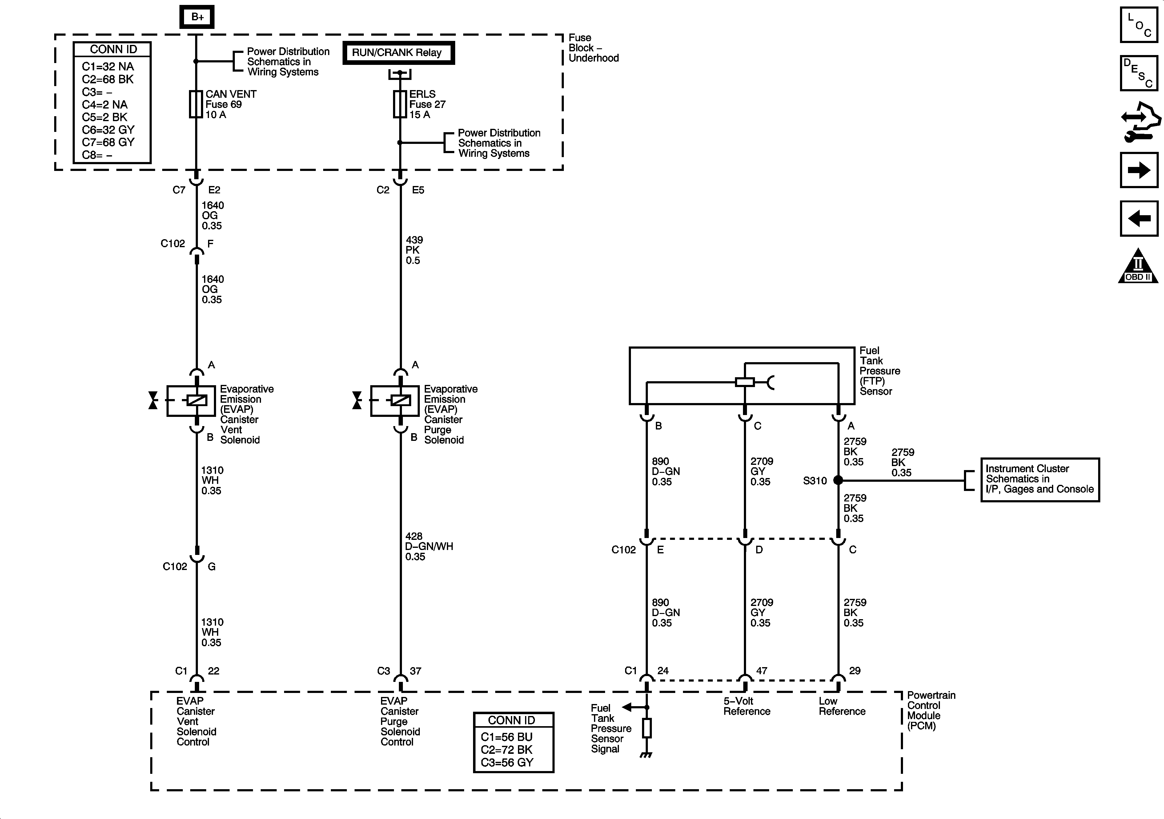
Fuel Controls - EVAP Controls


Object Number: 1696954  Size: FS
Master Electrical Component List
Fuel System Description
Body Control Module (BCM) Programming/RPO Configuration
Controlled/Monitored Sub-System References
Fuel Controls - Fuel Injectors
Engine Controls Schematic Icons
B+ Bus - Underhood Fuse Block
RUN/CRANK RELAY BUS - 3 of 3, CRUISE, SIR, and TRANS Fuses
Gages
Figure 10:

Controlled/Monitored Subsystem and Transmission References
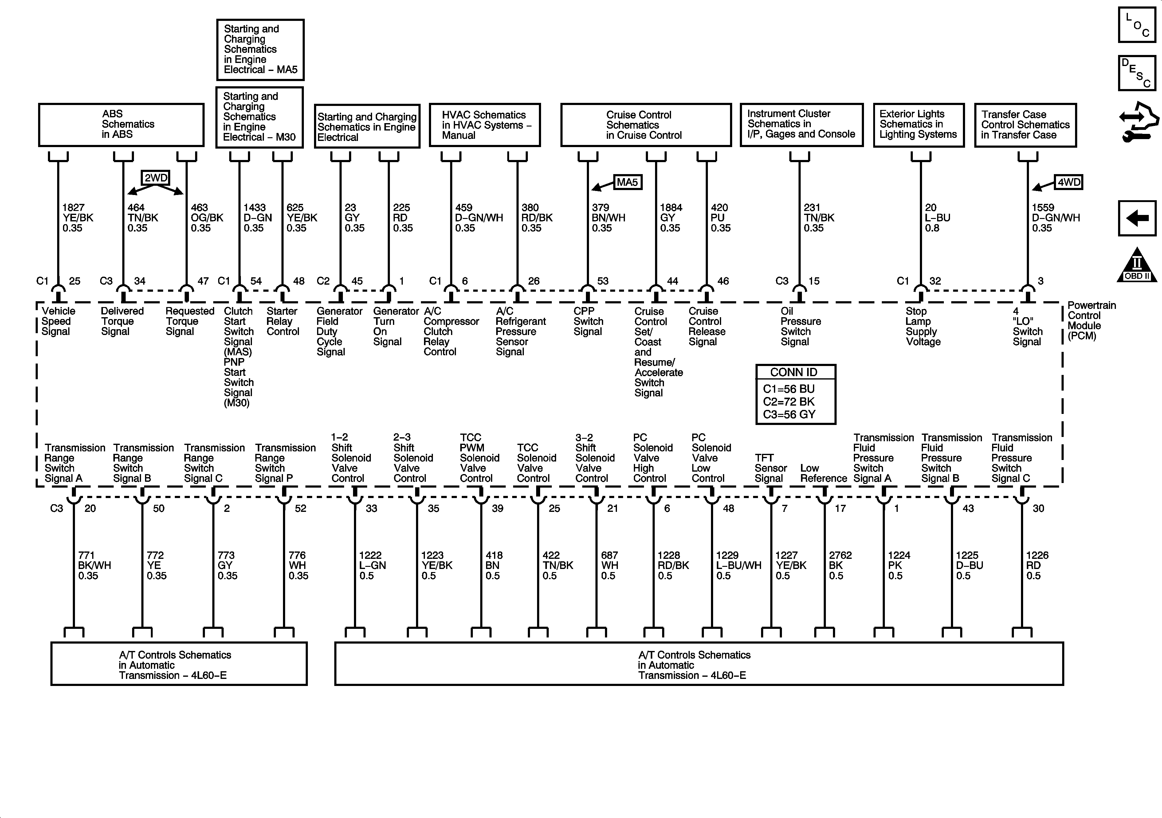

Object Number: 1696959  Size: FS
Master Electrical Component List
Camshaft Actuator System Description
Body Control Module (BCM) Programming/RPO Configuration
Fuel Controls - Fuel Pressure Sensor/Regulator
Engine Controls Schematic Icons
Power, Ground, and Electric Brake Control Module
Starting System - MA5
Starting System - M30
Charging System
Compressor Controls - C60
Cruise Control Schematics
Indicators
Stop Lamps and License Lamps
Transfer Case Encoder Motor
Switches and VSS
Transmission Controls