Procedure for Upgrading a Vehicle without XM Satellite Radio to an XM-Equipped Vehicle

| Subject: | Procedure for Upgrading a Vehicle without XM Satellite Radio to an XM-Equipped Vehicle |
| Models: | 2006-2008 Chevrolet Cobalt |
| 2007-2008 Pontiac G5 |
| with OnStar® (RPO UE1) and Either US8 or US9 Radio |
The purpose of this bulletin is to provide information on upgrading the above vehicles with no XM satellite radio to an XM-equipped vehicle. The XM accessory kit, P/N 17800594, which is available for use in the Chevy HHR, will also work on the Cobalt and G5 vehicles. The instruction sheet included in the kit, although it is for the HHR, can be used as a reference in addition to the step-by-step instructions below.
Important: Do not install this XM accessory kit on a non-OnStar® equipped vehicle or any vehicle equipped with a U1C radio.
XM Accessory Kit Installation Procedure
- Disconnect the negative battery cable.
- Remove the instrument panel (IP) trim plates from the left and right side of the IP center trim plate.
- Remove the IP center trim plate.
- Remove the radio and disconnect the electrical connectors.
- Remove both of the front floor console extension trim panels.
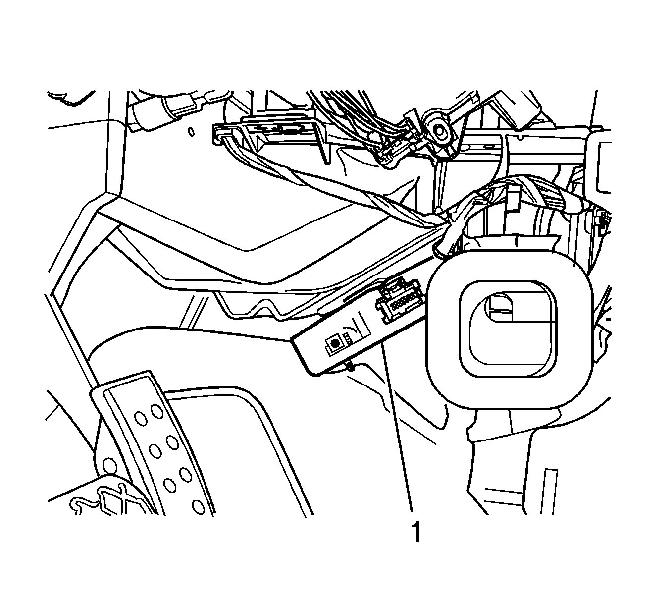
- Using Adhesion Promoter, P/N 12378462 (in Canada, use P/N 10953554), which is not included with the kit, wipe the heater case area thoroughly. The adhesion promoter is necessary to ensure a good bond is made and the XM receiver (1) is retained properly. Refer to the above illustration.
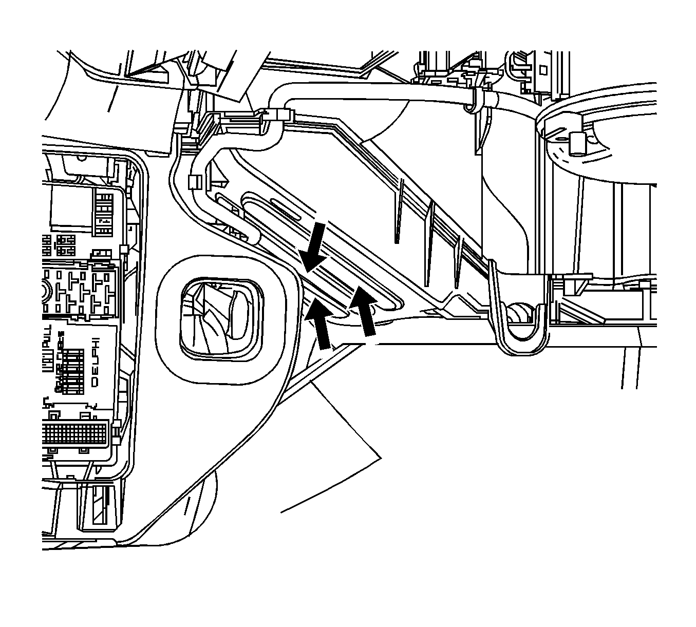
- Using the dual lock fastening tape, included in the kit, cut and apply the tape to the XM receiver as outlined in step 10 of the HHR instruction sheet.
- Remove the backing tape from the dual lock on the module and carefully insert the receiver into the cavity between the floor and the heater case. The connector end should point toward the driver's (left) side of the vehicle and the taped side toward the heater case. Refer to the above illustration.
- Using the XM accessory wiring harness, route the 16-way connector through the opening behind the radio down toward the XM receiver and connect the harness to the receiver.
- With the opposite end of the harness, connect the vehicle's 16-way and 14-way connectors in to the 30-way accessory harness connector. Connect the 16-way and 14-way connectors on the new harness to the radio. Pull the additional wiring harness length into the IP, gather the wires together and wrap tightly with electrical tape. Tie strap or tape this bundle to an existing harness or bracket so the harness will not rattle or chafe on sharp surfaces.
- Reinstall the radio.
- Remove the left side windshield pillar molding.
- Remove the left center pillar molding.
- Remove the rear quarter upper trim panel.
- Lower the rear of the headliner. Use care when lowering the headliner.
- Remove the existing roof-mounted antenna.
- Remove the bolt and spacer from the new antenna and install the antenna to the roof. Install the spacer and tighten the bolt.
- Using the new antenna coax cable (long cable), connect the cable to the antenna. Reconnect the other antenna connector(s).
- Remove the left side IP end cap trim panel.
- Remove the left knee bolster trim panel and reinforcement panel (if equipped).
- Route the antenna coax cable along the left side of the headliner, down the A-pillar into the left side of the IP, across the lower IP area down to and connect the cable to the XM receiver.
- Depending on the vehicle configuration (i.e. 2-door, 4-door, with or without sunroof), you may also need to connect the short coax cable to the long cable to have sufficient cable length. Then connect this cable to the XM receiver.
- Verify that all connectors are in place and reconnect the negative battery cable.
- Test the function of the radio and XM by pressing the BAND button until XM is displayed. You should be able to hear the 'preview station.' If not, follow the digital radio receiver setup section of the service manual.
- Follow the steps in the XM activation instructions to activate the XM system.
- After verifying that everything functions correctly, reinstall all of the trim as they were removed.


Important: Proper placement of the module is critical to it being retained to the heater case. The dual lock should be fastened to the "raised" portion molded into the heater case in the areas shown by the arrows in the above illustration. Once in place, apply firm pressure to the receiver to ensure good contact is made and the adhesive backing on the dual lock is thoroughly engaged to the heater case.
Tighten
Tighten the bolt to 9 N·m (79 lb in).
Important: If the vehicle is equipped with roof rail air bags (RPO ASF), it is critical that the coax cable be routed inboard, toward the center the vehicle in the roof area and also inboard on the A-pillar area so as to clear the roof rail air bags.
