Circuit Description
The body control module (BCM) monitors the voltage level on the supply voltage circuit of the REAR DEFOG relay. The voltage level should be low while the REAR DEFOG relay is de-energized. The voltage will be near system voltage when the BCM energizes the REAR DEFOG relay.
DTC Descriptor
This diagnostic procedure supports the following DTC:
DTC B0285 Electric Rear Defrost Circuit Low
Conditions for Running the DTC
| • | The ignition is ON. |
| • | Fog lights are active, if equipped. |
Conditions for Setting the DTC
The BCM detects a low voltage level on the supply circuit of the REAR DEFOG relay when the relay is energized.
Action Taken When the DTC Sets
The rear window defogger will be disabled until the condition is no longer present.
Conditions for Clearing the DTC
| • | This DTC will change from current to history when the fault is no longer present. |
| • | A history DTC will clear after 100 consecutive ignition cycles if the condition for the malfunction is no longer present. |
Test Description
The numbers below refer to the step numbers on the diagnostic table.
-
Listen for an audible click when the REAR DEFOG relay operates. Command both the ON and OFF states. Repeat the commands as necessary.
-
Verifies that the BCM is providing voltage to the REAR DEFOG relay.
-
Tests for a short to ground on the supply voltage circuit of the REAR DEFOG relay coil.
Step | Action | Yes | No |
|---|---|---|---|
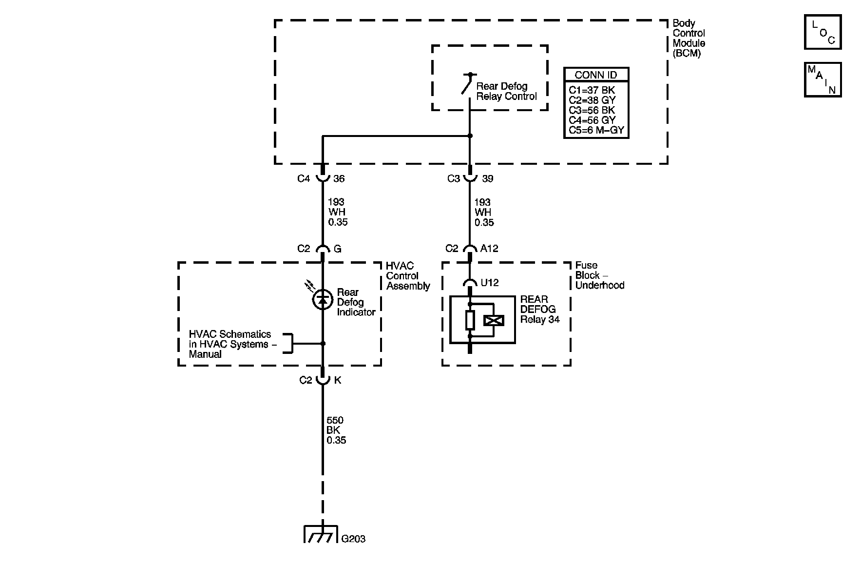
Schematic Reference: Defogger Schematics Connector End View Reference: Stationary Windows Connector End Views | |||
1 | Did you perform the Diagnostic System Check - Vehicle? | Go to Step 2 | Go to Diagnostic System Check - Vehicle in Vehicle DTC Information |
Do you hear a click when you command the REAR DEFOG relay ON and OFF? | Go to Testing for Intermittent Conditions and Poor Connections in Wiring Systems | Go to Step 3 | |
Does the test lamp illuminate? | Go to Step 4 | Go to Step 5 | |
4 |
Does the test lamp turn ON and OFF with each command? | Go to Step 7 | Go to Step 9 |
Test the supply voltage circuit of the REAR DEFOG relay for a short to ground. Refer to Circuit Testing and Wiring Repairs in Wiring Systems. Did you find and correct the condition? | Go to Step 12 | Go to Step 6 | |
6 | Test the supply voltage circuit of the rear window defogger indicator for a short to ground. Refer to Circuit Testing and Wiring Repairs in Wiring Systems. Did you find and correct the condition? | Go to Step 12 | Go to Step 8 |
7 | Inspect for poor connections at the REAR DEFOG relay. Refer to Testing for Intermittent Conditions and Poor Connections and Connector Repairs in Wiring Systems. Did you find and correct the condition? | Go to Step 12 | Go to Step 10 |
8 | Inspect for poor connections at the harness connector of the BCM. Refer to Testing for Intermittent Conditions and Poor Connections and Connector Repairs in Wiring Systems. Did you find and correct the condition? | Go to Step 12 | Go to Step 11 |
9 | Repair an open or high resistance in the ground circuit of the REAR DEFOG relay. Refer to Wiring Repairs in Wiring Systems. Did you complete the repair? | Go to Step 12 | -- |
10 | Replace the REAR DEFOG relay. Did you complete the replacement? | Go to Step 12 | -- |
11 | Replace the BCM. Refer to Control Module References in Computer/Integrating Systems for replacement, setup, and programming. Did you complete the replacement? | Go to Step 12 | -- |
12 |
Does the DTC reset? | Go to Step 2 | System OK |
