GM Service Manual Online
For 1990-2009 cars only
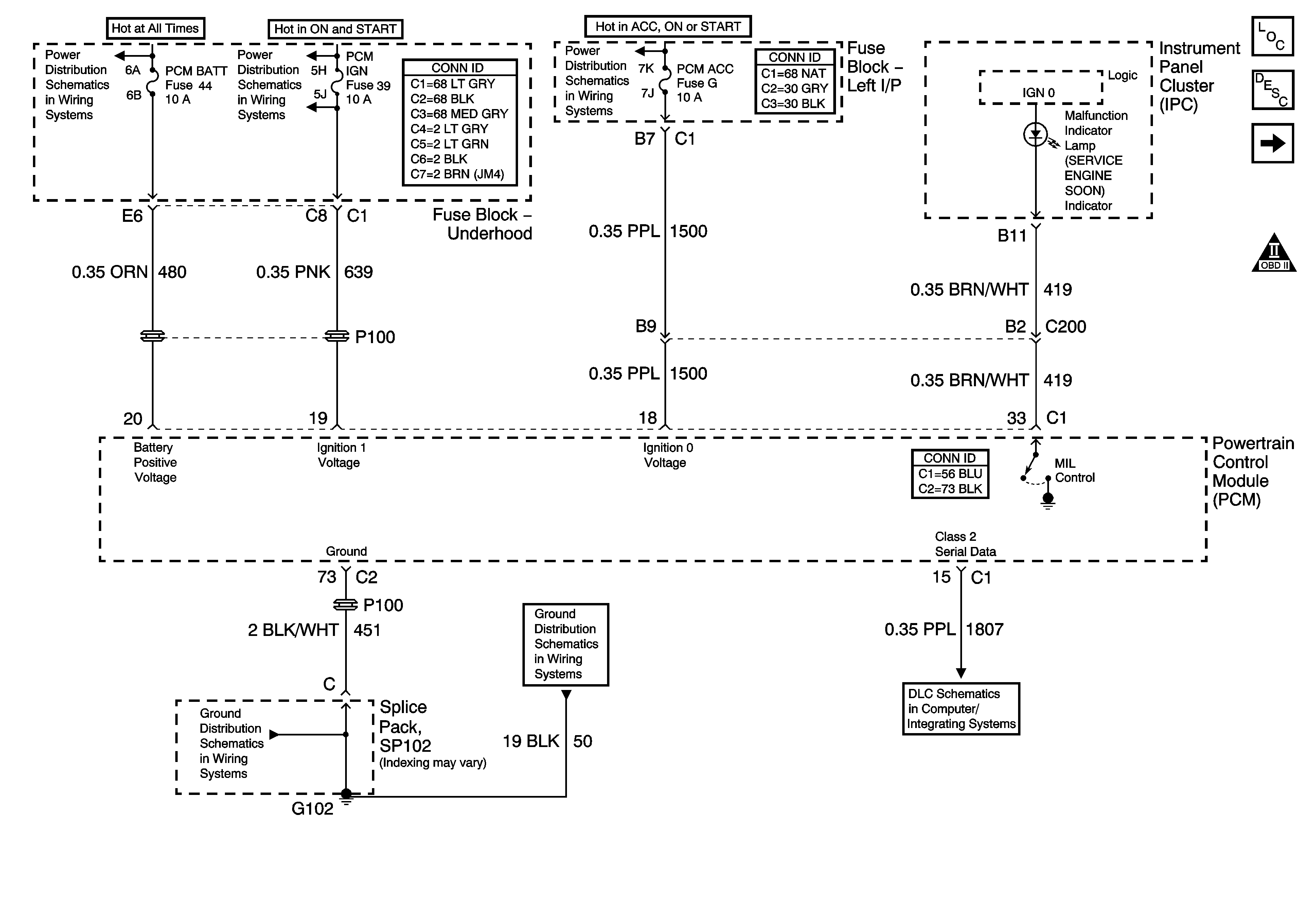
Figure 1:

Power, Ground, Serial Data and MIL


Object Number: 1493955  Size: FS
Master Electrical Component List
Powertrain Control Module Description
5-Volt and Low Reference Bussing
Engine Controls Schematic Icons
AUX PWR/CIGAR, PRK LMS, and PCM BATT Fuses
IGN MOD, B/U LMP, PCM IGN, INJR, A/C FBC, AUTO TRANS, ABS IGN Fuses
IGN BATT 1, IGN SW BATT 2, Ignition Switch
SP102
SP102
Data Link Connector (DLC) Schematics
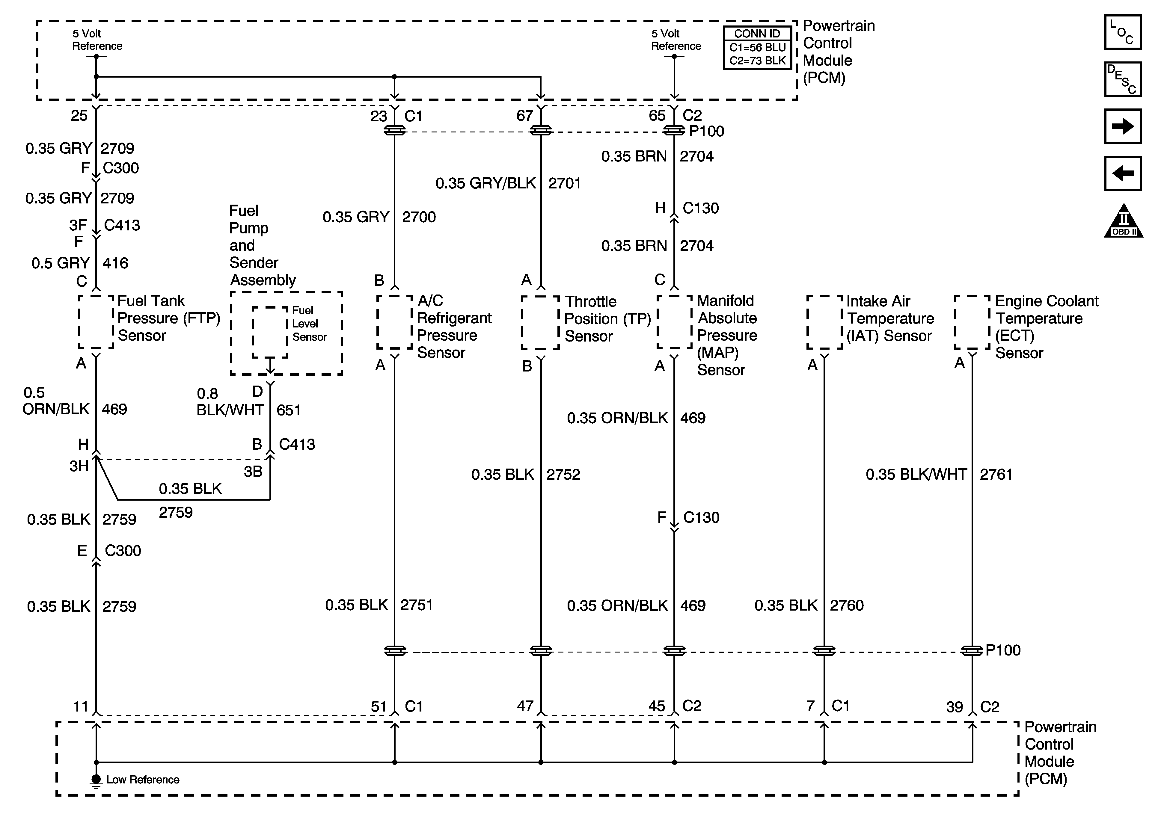
Figure 2:

5-Volt and Low Reference Bussing


Object Number: 1199972  Size: FS
Master Electrical Component List
Powertrain Control Module Description
Engine Data Sensors - Pressure and Temperature
Power, Ground, Serial Data and MIL
Engine Controls Schematic Icons
Figure 3:

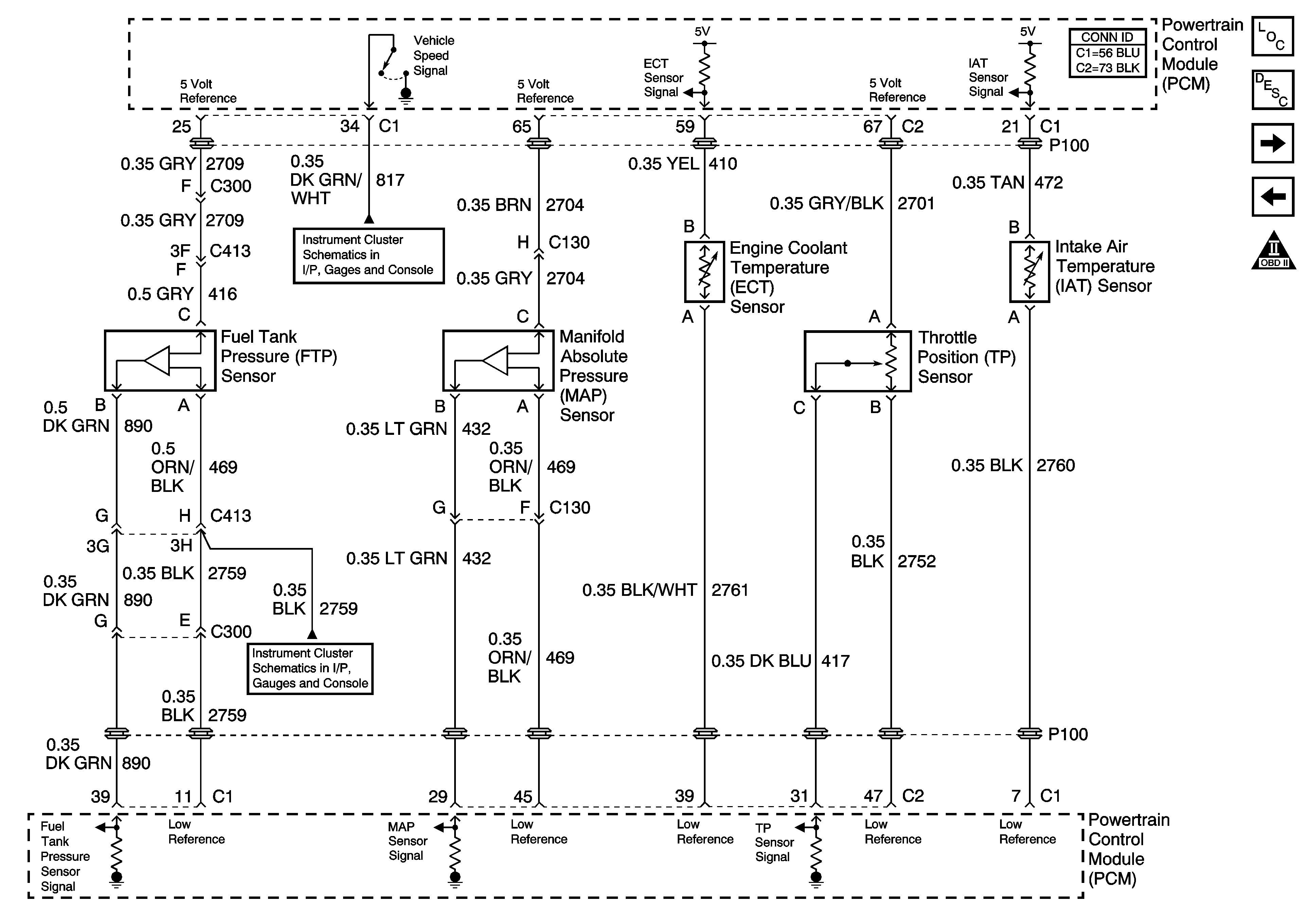
Engine Data Sensors - Pressure and Temperature


Object Number: 1199974  Size: FS
Master Electrical Component List
Powertrain Control Module Description
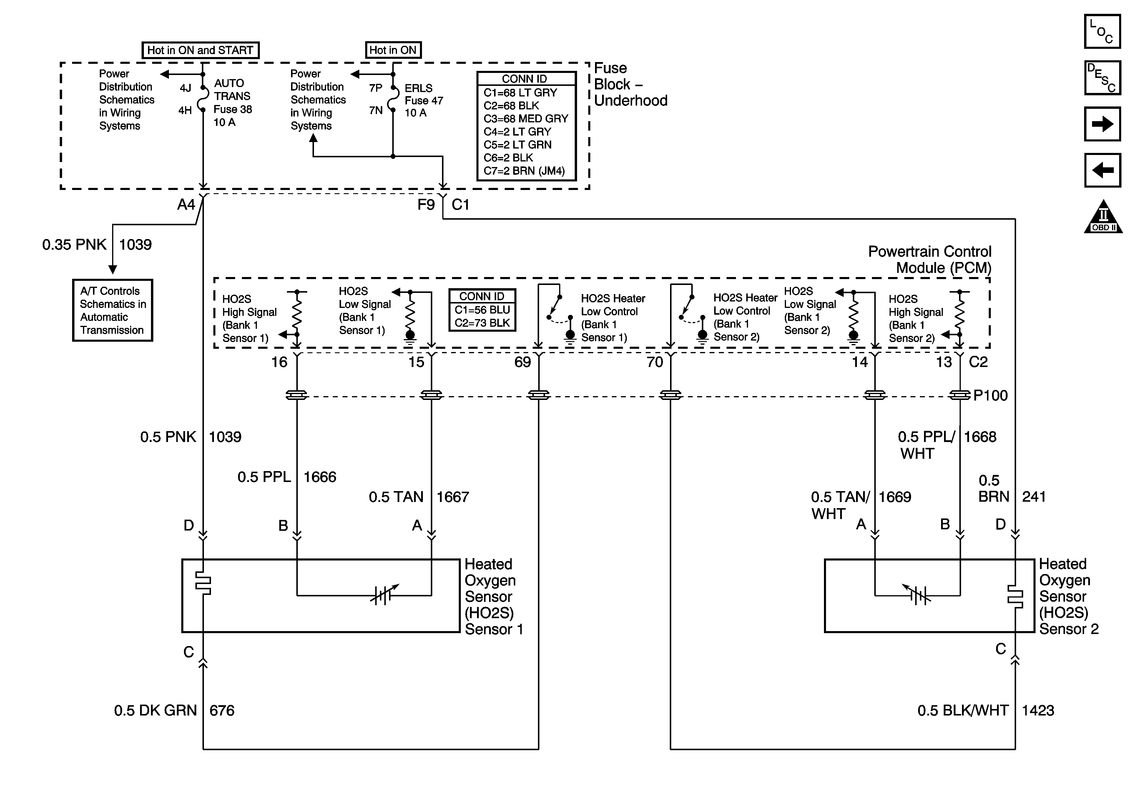
Engine Data Sensors - Heated Oxygen Sensors
5-Volt and Low Reference Bussing
Engine Controls Schematic Icons
Power and Grounds
Indicators and Communication
Figure 4:

Engine Data Sensors - Heated Oxygen Sensors


Object Number: 1199976  Size: FS
Master Electrical Component List
Powertrain Control Module Description
Ignition System
Engine Data Sensors - Pressure and Temperature
Engine Controls Schematic Icons
IGN MOD, B/U LMP, PCM IGN, INJR, A/C FBC, AUTO TRANS, ABS IGN Fuses
HTR A/C IGN and ERLS Fuses
Shift Solenoids
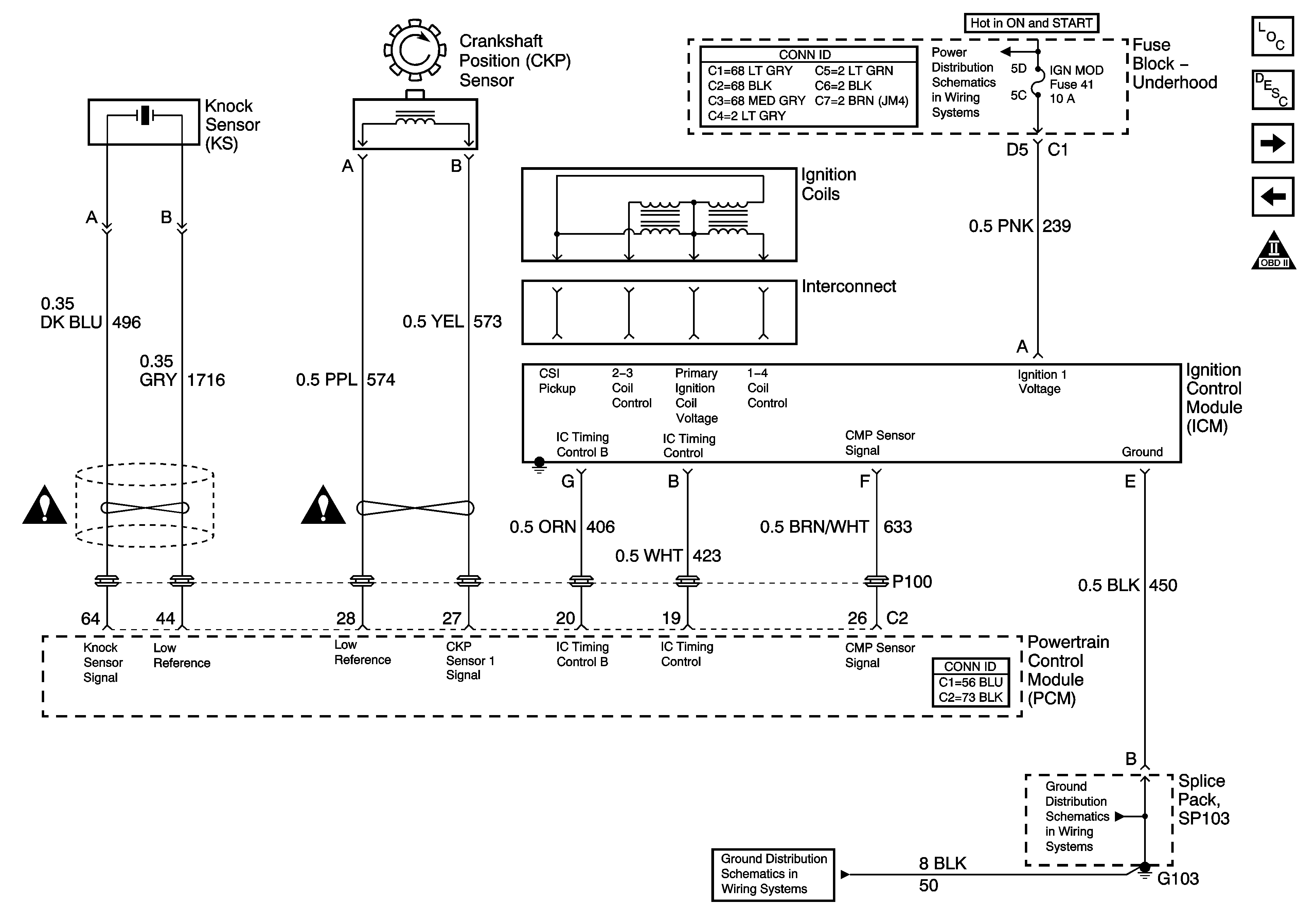
Figure 5:

Ignition System


Object Number: 1199977  Size: FS
Master Electrical Component List
Electronic Ignition (EI) System Description
Fuel Pump Controls
Engine Data Sensors - Heated Oxygen Sensors
Engine Controls Schematic Icons
IGN MOD, B/U LMP, PCM IGN, INJR, A/C FBC, AUTO TRANS, ABS IGN Fuses
Engine Controls Schematic Icons
SP103
SP103
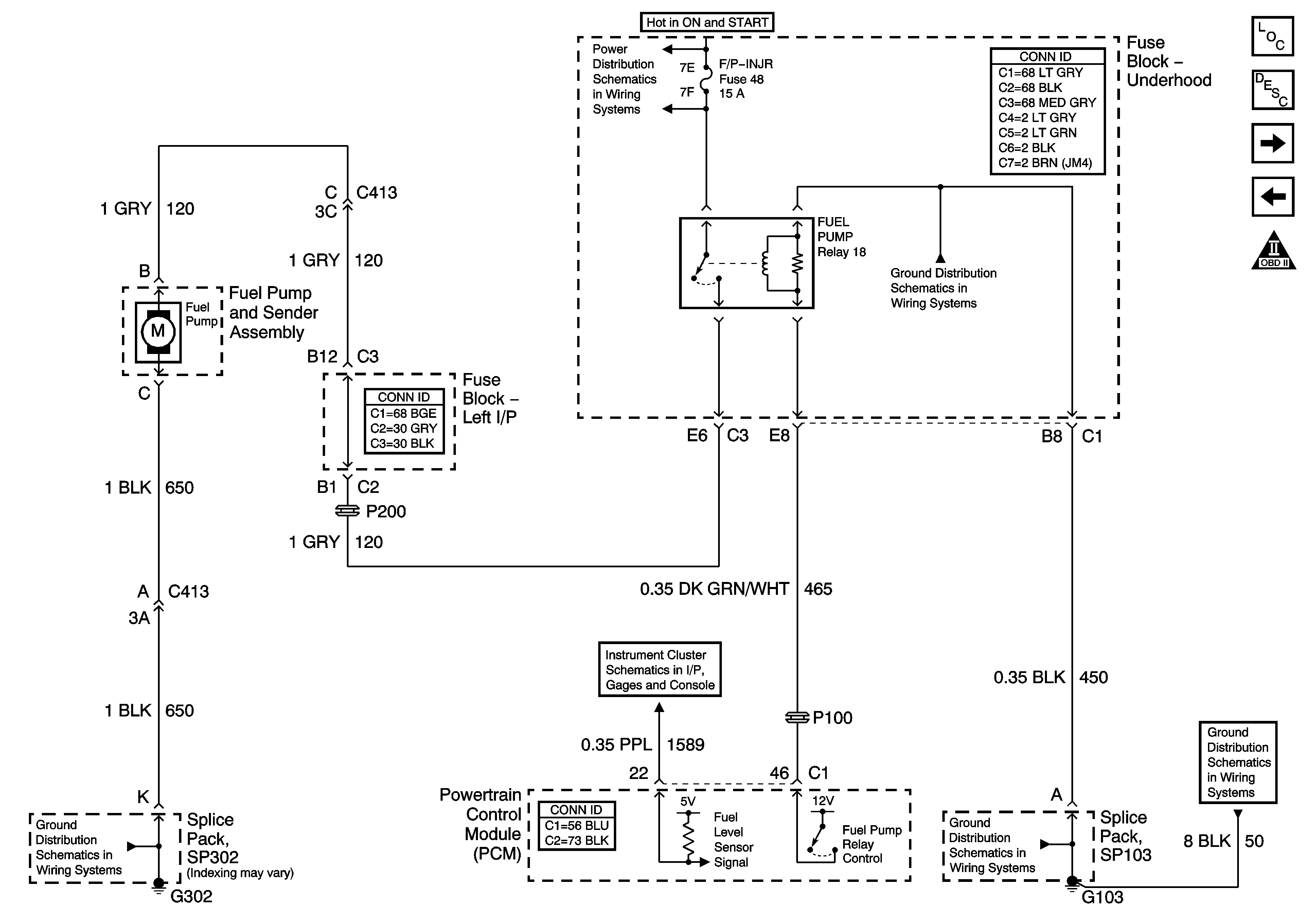
Figure 6:

Fuel Pump Controls


Object Number: 1199978  Size: FS
Master Electrical Component List
Fuel System Description
Fuel Injectors
Ignition System
Engine Controls Schematic Icons
IGN MOD, B/U LMP, PCM IGN, INJR, A/C FBC, AUTO TRANS, ABS IGN Fuses
SP103
SP302
Indicators and Communication
SP103
SP103
Figure 7:

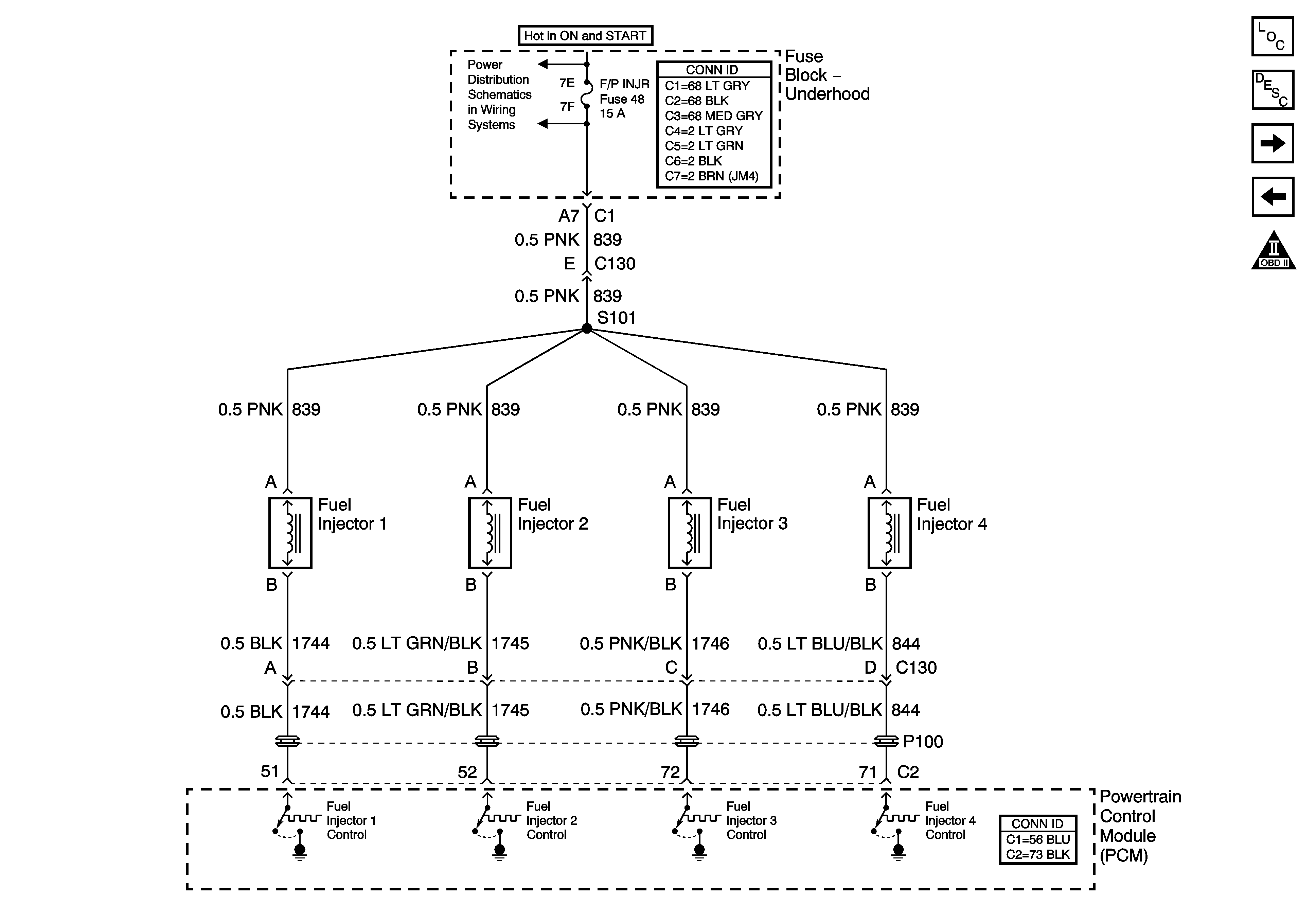
Fuel Injectors


Object Number: 1199979  Size: FS
Master Electrical Component List
Fuel System Description
EVAP and IAC Controls
Fuel Pump Controls
Engine Controls Schematic Icons
IGN MOD, B/U LMP, PCM IGN, INJR, A/C FBC, AUTO TRANS, ABS IGN Fuses
Figure 8:

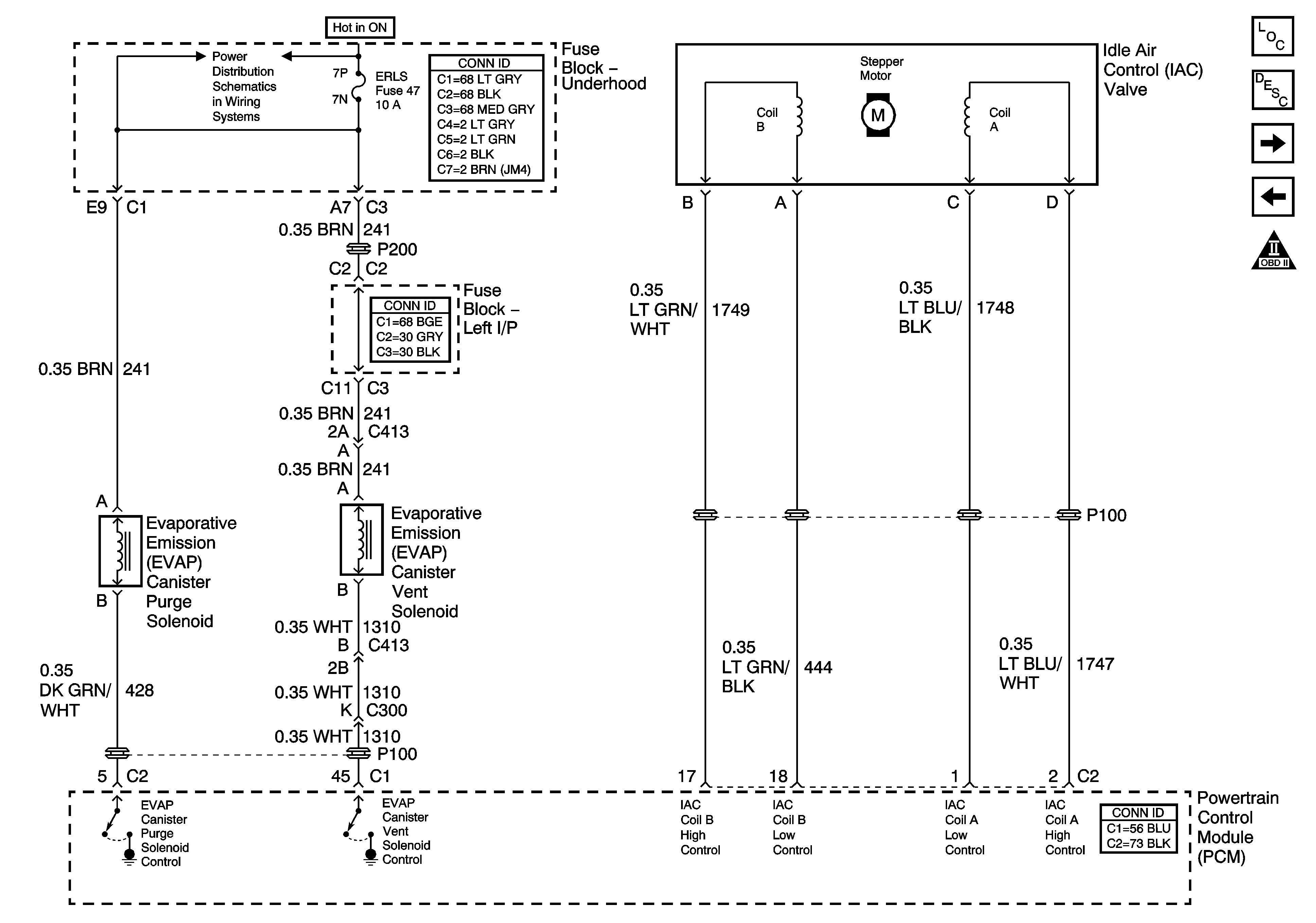
EVAP and IAC Controls


Object Number: 1199980  Size: FS
Master Electrical Component List
Powertrain Control Module Description
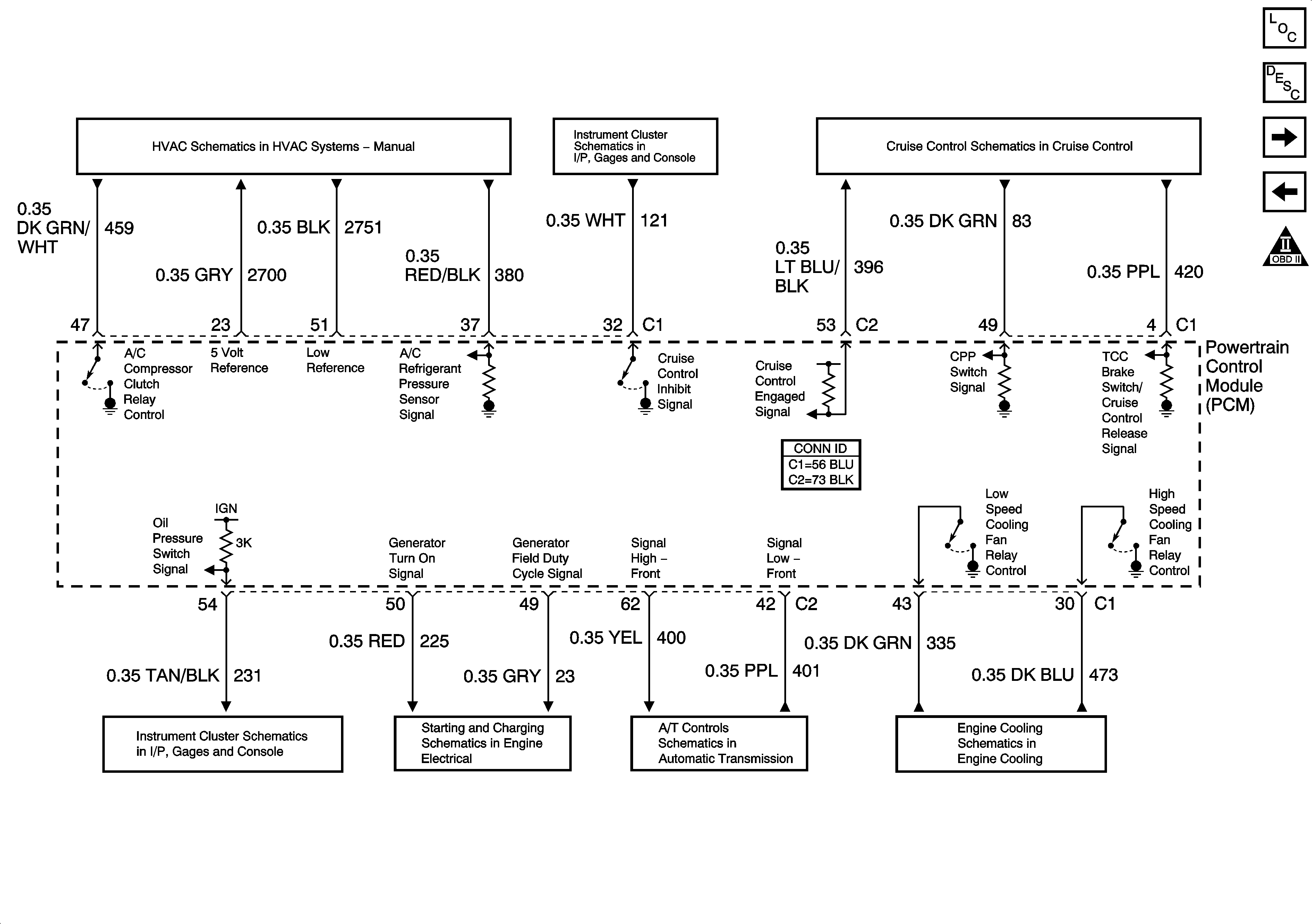
Controlled/Monitored Subsystem References
Fuel Injectors
Engine Controls Schematic Icons
HTR A/C IGN and ERLS Fuses
Figure 9:

Controlled/Monitored Subsystem References


Object Number: 1199982  Size: FS
Master Electrical Component List
Powertrain Control Module Description
EVAP and IAC Controls
Transmission References
Engine Controls Schematic Icons
A/C Compressor Controls
Power and Grounds
Brake Switch and Inhibit Signals
Indicators and Communication
Charging System
Shift Solenoids
Cooling Fans
Figure 10:

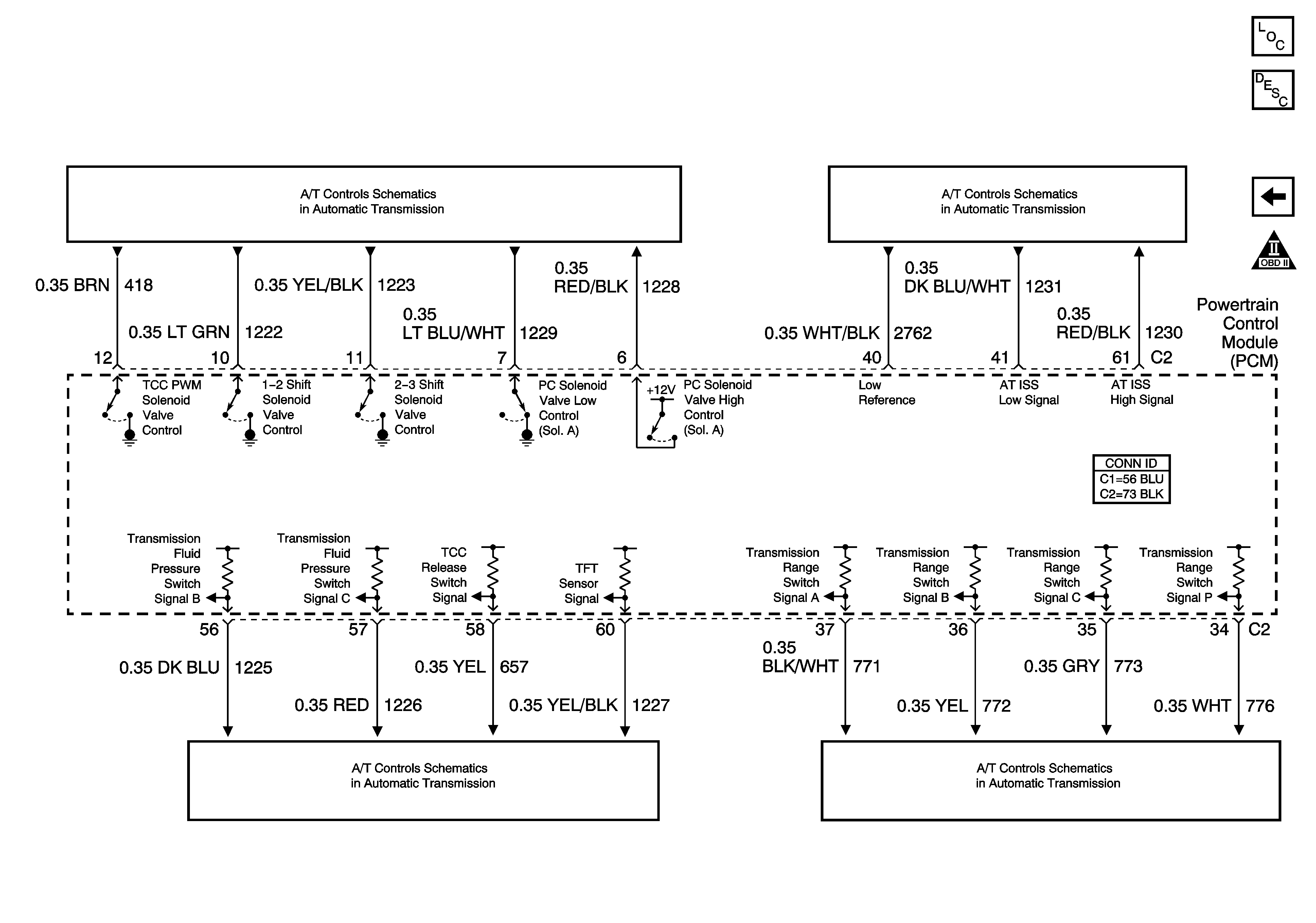
Transmission References


Object Number: 1199984  Size: FS
Master Electrical Component List
Powertrain Control Module Description
Controlled/Monitored Subsystem References
Engine Controls Schematic Icons
Shift Solenoids
Transmission Switches
Park/Neutral Position (PNP) Switch