Shock Absorber Replacement Pick-up
Removal Procedure
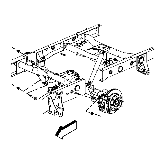
- Raise and support the vehicle. Refer to Lifting and Jacking the Vehicle in General Information.
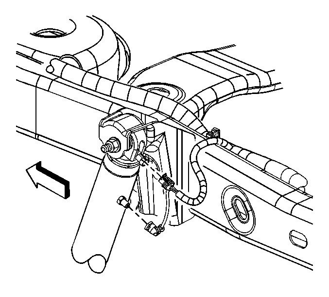
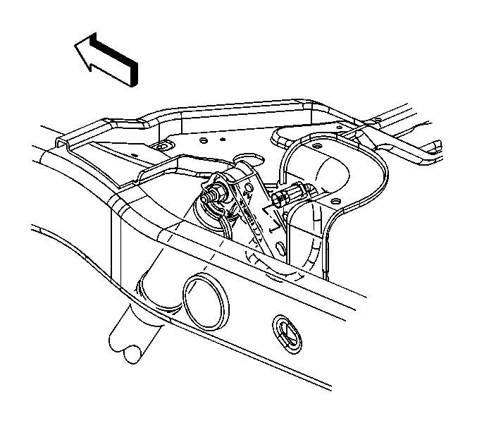
- Disconnect the electrical connector if equipped with Selectable Ride.
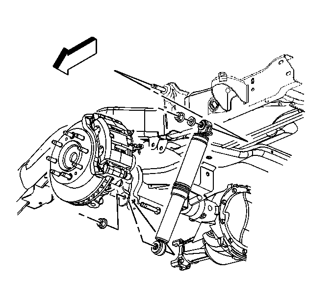
- Remove the upper shock absorber nut and the bolt.
- Remove the lower shock absorber nut and the bolt.
- Remove the shock absorber.
Installation Procedure
- Install the shock absorber.
- Install the upper shock absorber nut and bolt.
- Install the lower shock absorber nut and bolt.
- Connect the electrical connector if equipped with Selectable Ride.
- Remove the safety stands.
- Lower the vehicle.
Notice: Use the correct fastener in the correct location. Replacement fasteners must be the correct part number for that application. Fasteners requiring replacement or fasteners requiring the use of thread locking compound or sealant are identified in the service procedure. Do not use paints, lubricants, or corrosion inhibitors on fasteners or fastener joint surfaces unless specified. These coatings affect fastener torque and joint clamping force and may damage the fastener. Use the correct tightening sequence and specifications when installing fasteners in order to avoid damage to parts and systems.
Tighten
Tighten the nuts to 95 N·m (70 lb ft).
Shock Absorber Replacement 15 Series Utility
Removal Procedure
- Raise and support the vehicle. Refer to Lifting and Jacking the Vehicle in General Information.
- Disconnect the electrical connector and air line if equipped with Real Time Damping (RTD).
- Support the rear axle.
- Disconnect the RTD sensor (if equipped). Refer to Electronic Suspension Rear Position Sensor Replacement - Left Side or Electronic Suspension Rear Position Sensor Replacement - Right Side in Real Time Damping (RTD).
- Remove the upper shock absorber nut and the bolt.
- Remove the lower shock absorber nut and the bolt.
- Remove the shock absorber.
Installation Procedure
- Install the shock absorber.
- Install the upper shock absorber nut and bolt.
- Install the lower shock absorber nut and bolt.
- Connect the electrical connector and air line if equipped with RTD.
- Connect the RTD sensor, if equipped. Refer to Electronic Suspension Rear Position Sensor Replacement - Left Side or Electronic Suspension Rear Position Sensor Replacement - Right Side in Real Time Damping (RTD).
- Remove the support from the rear axle.
- Remove the safety stands.
- Lower the vehicle.
Notice: Use the correct fastener in the correct location. Replacement fasteners must be the correct part number for that application. Fasteners requiring replacement or fasteners requiring the use of thread locking compound or sealant are identified in the service procedure. Do not use paints, lubricants, or corrosion inhibitors on fasteners or fastener joint surfaces unless specified. These coatings affect fastener torque and joint clamping force and may damage the fastener. Use the correct tightening sequence and specifications when installing fasteners in order to avoid damage to parts and systems.
Tighten
Tighten the nuts to 95 N·m (70 lb ft).
Shock Absorber Replacement 15 Series Utility w/G65
Removal Procedure
Important: This shock absorber is a very high pressure gas charged component. Never attempt to tether or manually compress the shock. Replacement shocks are supplied in the fully extended position.
- Raise and support the vehicle. Refer to Lifting and Jacking the Vehicle General Information.
- Support the rear axle.
- Remove the upper shock absorber nut and the bolt.
- Remove the lower shock absorber nut and the bolt.
- Lower the rear axle to allow the removal of the shock absorber.
- Remove the shock absorber.
Installation Procedure
- Install the shock absorber.
- Install the upper shock absorber nut and bolt.
- Raise the rear axle to allow the installation of the lower through bolt.
- Install the lower shock absorber nut and bolt.
- Remove the support from the rear axle.
- Remove the safety stands.
- Lower the vehicle.
Notice: Use the correct fastener in the correct location. Replacement fasteners must be the correct part number for that application. Fasteners requiring replacement or fasteners requiring the use of thread locking compound or sealant are identified in the service procedure. Do not use paints, lubricants, or corrosion inhibitors on fasteners or fastener joint surfaces unless specified. These coatings affect fastener torque and joint clamping force and may damage the fastener. Use the correct tightening sequence and specifications when installing fasteners in order to avoid damage to parts and systems.
Tighten
Tighten the nuts to 95 N·m (70 lb ft).
Shock Absorber Replacement 25 Series Utility
Removal Procedure
- Raise and support the vehicle. Refer to Lifting and Jacking the Vehicle in General Information.
- Support the rear axle.
- Disconnect the Real Time Damping (RTD) electrical connector at the pigtail connector left side only, if equipped.
- Disconnect the RTD electrical connector at the top of the right side shock, if equipped.
- Disconnect the RTD sensor (if equipped). Refer to Electronic Suspension Rear Position Sensor Replacement - Left Side or Electronic Suspension Rear Position Sensor Replacement - Right Side in Real Time Damping (RTD).
- Remove the upper shock absorber nut and the bolt.
- Remove the lower shock absorber nut and the bolt.
- Remove the shock absorber.
Installation Procedure
- Install the shock absorber.
- Install the upper shock absorber nut and bolt.
- Install the lower shock absorber nut and bolt.
- Remove the rear axle support.
- Connect the RTD sensor (if equipped). Refer to Electronic Suspension Rear Position Sensor Replacement - Left Side or Electronic Suspension Rear Position Sensor Replacement - Right Side in Real Time Damping (RTD).
- Connect the RTD electrical connector at the top of the right side shock, if equipped.
- Connect the RTD electrical connector at the pigtail connector left side only (if equipped).
- Remove the safety stands.
- Lower the vehicle.
Notice: Use the correct fastener in the correct location. Replacement fasteners must be the correct part number for that application. Fasteners requiring replacement or fasteners requiring the use of thread locking compound or sealant are identified in the service procedure. Do not use paints, lubricants, or corrosion inhibitors on fasteners or fastener joint surfaces unless specified. These coatings affect fastener torque and joint clamping force and may damage the fastener. Use the correct tightening sequence and specifications when installing fasteners in order to avoid damage to parts and systems.
Tighten
Tighten the nuts to 95 N·m (70 lb ft).
