Circuit Description
The Security Indicator Inoperative check is designed to find out the reason the Security indicator is not illuminating. However, the Theft Deterrent System Diagnostic System Check must always be the starting point for all Passlock system troubleshooting.
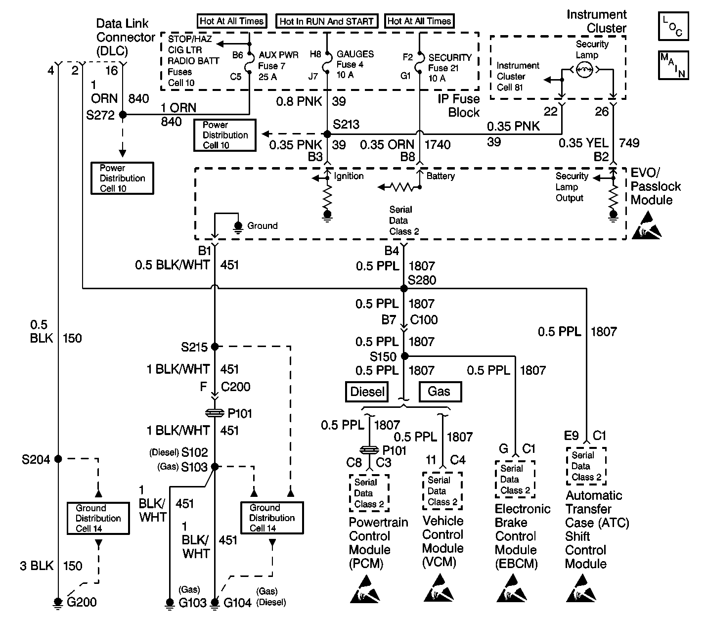
The diagnostics in this table are designed to troubleshoot non DTC troubles. For example battery power, ignition 1 input, ground, and shorted or open SECURITY indicator circuit.
Diagnostic Aids
| • | Perform a visual inspection of the wiring and the connectors. |
| • | Refer to Intermittents and Poor Connections . |
Test Description
The numbers below refer to the numbers in the diagnostic table.
-
This step determines if there is power available to the instrument cluster.
-
This step tests for continuity in circuit 749.
-
This step tests for a short to battery in circuit 749.
-
This step tests for an open in circuit 651.
-
This step verifies if the gauges fuse randomly opened.
-
This step determines if there is a short to ground in the EVO/Passlock module.
-
This step tests for voltage at the battery side of the Security indicator.
Step | Action | Value(s) | Yes | No | ||||
|---|---|---|---|---|---|---|---|---|
1 | Did you perform the Passlock Diagnostic System Check? | -- | Go to Step 2 | |||||
2 |
Is the Brake warning telltale or the Check Gauges telltale on? | -- | Go to Step 3 | Go to Step 11 | ||||
3 |
Is the bulb open? | -- | Go to Step 4 | Go to Step 5 | ||||
4 | Replace the SECURITY indicator bulb. Is the repair complete? | -- | -- | |||||
5 |
Is the resistance within the specified value? | 0-5 ohms | Go to Step 7 | Go to Step 6 | ||||
6 | Repair the open in circuit 749. Is the repair complete? | -- | -- | |||||
7 |
Is the voltage within the specified value? | 9-16 V | Go to Step 8 | Go to Step 9 | ||||
8 | Repair short to ignition in circuit 749. Is the repair complete? | -- | Go to Step 19 | -- | ||||
9 | Using the J 39200 , measure the resistance from connector terminal B1 of the EVO/Passlock module to ground. Is the resistance within the specified value? | 0-5 ohms | Go to Step 17 | Go to Step 10 | ||||
10 | Repair the open in circuit 651 between connector terminal B1 of the EVO/Passlock module and G103/G104. Is the repair complete? | -- | -- | |||||
11 | Test the gauges fuse. Is the gauges fuse open? | -- | Go to Step 12 | Go to Step 15 | ||||
12 |
Did the gauges fuse open? | -- | Go to Step 13 | |||||
13 |
Did the gauges fuse open? | -- | Go to Step 14 | Go to Step 19 | ||||
14 |
Is the repair complete? | -- | -- | |||||
15 |
Is the voltage within the specified value? | 9-16 V | Go to Step 18 | Go to Step 16 | ||||
16 | Repair the open in circuit 39. Is the repair complete? | -- | -- | |||||
17 |
Did the Security telltale turn on? | -- | Go to Step 19 | Go to Step 18 | ||||
18 | Replace the instrument cluster. Is the repair complete? | -- | -- | |||||
19 | Replace the EVO/Passlock module. Refer to Theft Deterrent Module Replacement . Is the repair complete? | -- | Go to Step 20 | -- | ||||
20 |
Is the repair complete? | -- | -- |
