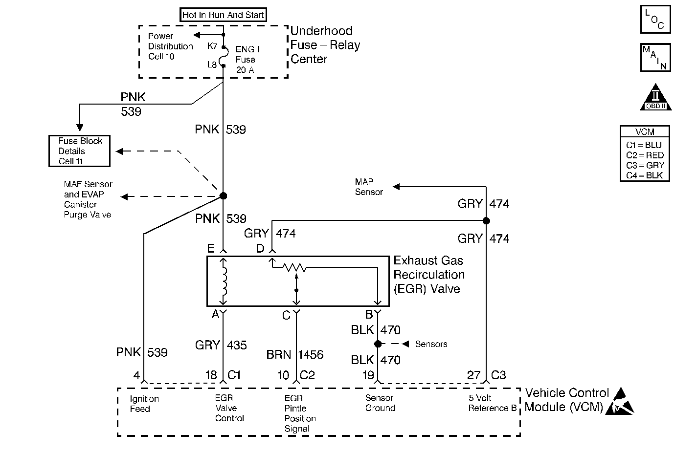
Circuit Description
The VCM constantly monitors the linear EGR valve pintle position sensor in order to ensure that the valve is responding properly to the commands from the VCM. The DTC P1406 is a type A DTC.
Conditions for Setting the DTC
The following condition will set the DTC:
| • | Ignition voltage greater than 9 volts |
| • | The difference between the actual EGR position and the desired EGR position is greater than 10 % for 10 seconds |
Action Taken When DTC Sets
If a current DTC P1406 sets during 2 consecutive test cycles, the VCM turns ON the MIL.
Conditions for Clearing the MIL/DTC
The VCM turns OFF the MIL after 3 consecutive driving trips without a fault condition present. A history DTC will clear if no fault conditions have been detected for 40 warm-up cycles (the coolant temperature has risen 22°C (40°F) from the start-up coolant temperature and the engine coolant temperature exceeds 71°C (160°F) during that same ignition cycle) or the scan tool clearing feature has been used.
Diagnostic Aids
A poor connection or rubbed-through wire insulation may cause an intermittent. Check for the following conditions:
| • | Poor connection or damaged harness - Inspect VCM harness connectors for backed out terminals at EGR Control signal circuit, 5 V reference circuit, EGR sensor ground circuit, or Pintle position circuit for the following items: |
| • | Improper mating |
| • | Broken locks |
| • | Improperly formed or damaged terminals |
| • | Poor terminal to wire connection |
| • | Damaged harness |
Intermittent test - If connections and harness check OK, monitor a digital voltmeter connected between affected terminals and ground while moving related connectors and wiring harness. If the failure is induced, the voltage reading will change.
Test Description
The numbers below refer to the step numbers on the diagnostic table.
-
Checks for an EGR valve sticking partially open or an incorrect pintle position sensor feedback signal.
-
This step determines if this DTC was set during an intermittent condition. If the fault that set this DTC is not present, check for other stored DTCs.
-
Checks the EGR valve driver in the VCM and the EGR Control circuit.
-
This checks for EGR Valve Ignition Feed at the EGR valve.
-
Clearing the DTC Information is a very important step in this diagnostic. This allows the EGR Valve to relearn a new minimum pintle position.
Step | Action | Value(s) | Yes | No |
|---|---|---|---|---|
1 |
Important: Before clearing the DTCs, use the scan tool in order to record the Freeze Frame and the Failure Records for reference. This data will be lost when the Clear DTC Information function is used. Was the Powertrain On-Board Diagnostic (OBD) System Check performed? | -- | ||
Does the scan tool display the specified value? | 0% | |||
Does the Actual EGR Position follow the Commanded Position? | 20%, 50%, 70%,100% | Go to Diagnostic Aids | ||
4 |
Does the Actual EGR Position fluctuate severely? | 30% | ||
Is the test light ON? | 100% | |||
Is the test light ON? | -- | |||
7 |
Was a problem found? | -- | ||
8 | Repair the faulty connections or open in the EGR Valve Control circuit as necessary. Refer to Wiring Repairs in Electrical Diagnosis. Is the action complete? | -- | -- | |
9 | Is DTC P0108 also set? | -- | Go to DTC P0108 Manifold Absolute Pressure (MAP) Sensor Circuit High Voltage | |
10 | Disconnect the EGR Valve electrical connector. Is the Actual EGR Valve Position at the specified value? | 0% | ||
11 | Check for a short to voltage in the EGR Pintle Position circuit. Was a problem found? | -- | ||
12 | Repair short to voltage in the EGR Pintle Position circuit. Refer to Wiring Repairs in Electrical Diagnosis. Is the action complete? | -- | -- | |
13 | Check for a blown EGR Ignition Feed fuse. Was the EGR Ignition Feed fuse blown? | -- | ||
14 | Replace EGR Ignition Feed fuse. Is the action complete? | -- | -- | |
15 | Repair the short to ground in the EGR Ignition Feed circuit. Refer to Wiring Repairs in Electrical Diagnosis. Is the action complete? | -- | -- | |
16 | Repair the open EGR Ignition Feed circuit. Refer to Wiring Repairs in Electrical Diagnosis. Is the action complete? | -- | -- | |
17 |
Is the test light ON? | -- | ||
18 |
Is the test light ON? | -- | ||
19 |
Is the test light ON? | -- | ||
20 | Repair short to ground in the EGR Valve Control circuit. Refer to Wiring Repairs in Electrical Diagnosis. Is the action complete? | -- | -- | |
21 | Check for a faulty connection at the EGR valve harness connector. Was a problem found? | -- | ||
22 | Repair the faulty connection at the EGR valve harness connector. Refer to Wiring Repairs in Electrical Diagnosis. Is the action complete? | -- | -- | |
23 | Connect a DMM J 39200 between the EGR Valve connector terminals B and D. Is the voltage near the specified value? | 5.0V | ||
24 | Connect a DMM J 39200 between the EGR harness connector terminal D and a known good ground. Is the voltage at the specified value? | 5.0V | ||
25 | Check for open in EGR Sensor Ground circuit and repair as necessary. Refer to Wiring Repairs in Electrical Diagnosis. Was repair necessary? | -- | ||
26 | Check for open in EGR 5 Volt reference circuit and repair as necessary. Refer to Wiring Repairs in Electrical Diagnosis. Was a repair necessary? | -- | ||
27 |
Is the test light ON? | -- | ||
28 | Check for a short to ground in the EGR Pintle Position circuit. Was a problem found? | -- | ||
29 | Repair the short to ground in the EGR Pintle Position circuit. Refer to Wiring Repairs in Electrical Diagnosis. Is the action complete? | -- | -- | |
30 | Using proper test adapters from Connector Test Adapter kit J 35616 , install a jumper between terminals D and C of the EGR harness connector. Is the Actual EGR Position near the specified value? | 100% | ||
31 |
Was a problem found? | -- | ||
32 | Repair the open or poor connection in the EGR pintle position circuit . Refer to Wiring Repairs in Electrical Diagnosis. Is the action complete? | -- | -- | |
33 | Replace the EGR valve. Refer to EGR Valve Replacement in Repair Instructions. Is the action complete? | -- | -- | |
34 |
Is the test light ON? | -- | ||
35 | Repair open in ignition feed circuit to Pin 4 of the C1 (Blue) VCM connector. Refer to Wiring Repairs in Electrical Diagnosis. Is the action complete? | -- | -- | |
36 | Check for poor connections at the VCM harness connectors and repair as necessary. Refer to Wiring Repairs in Electrical Diagnosis. Was a repair necessary? | -- | ||
37 |
Important: Program the new VCM. Refer to VCM Replacement/Programming in Repair Instructions. Replace the VCM. Is the action complete? | -- | -- | |
Does scan tool indicate that this diagnostic ran and passed? | -- | |||
39 | Use the scan tool in order to display the Capture Info and the Review Capture Info functions. Are there any DTCs displayed that have not been diagnosed? | -- | Go to the applicable DTC table | System OK |
