Refer to
AIR System - 7.4L California Only
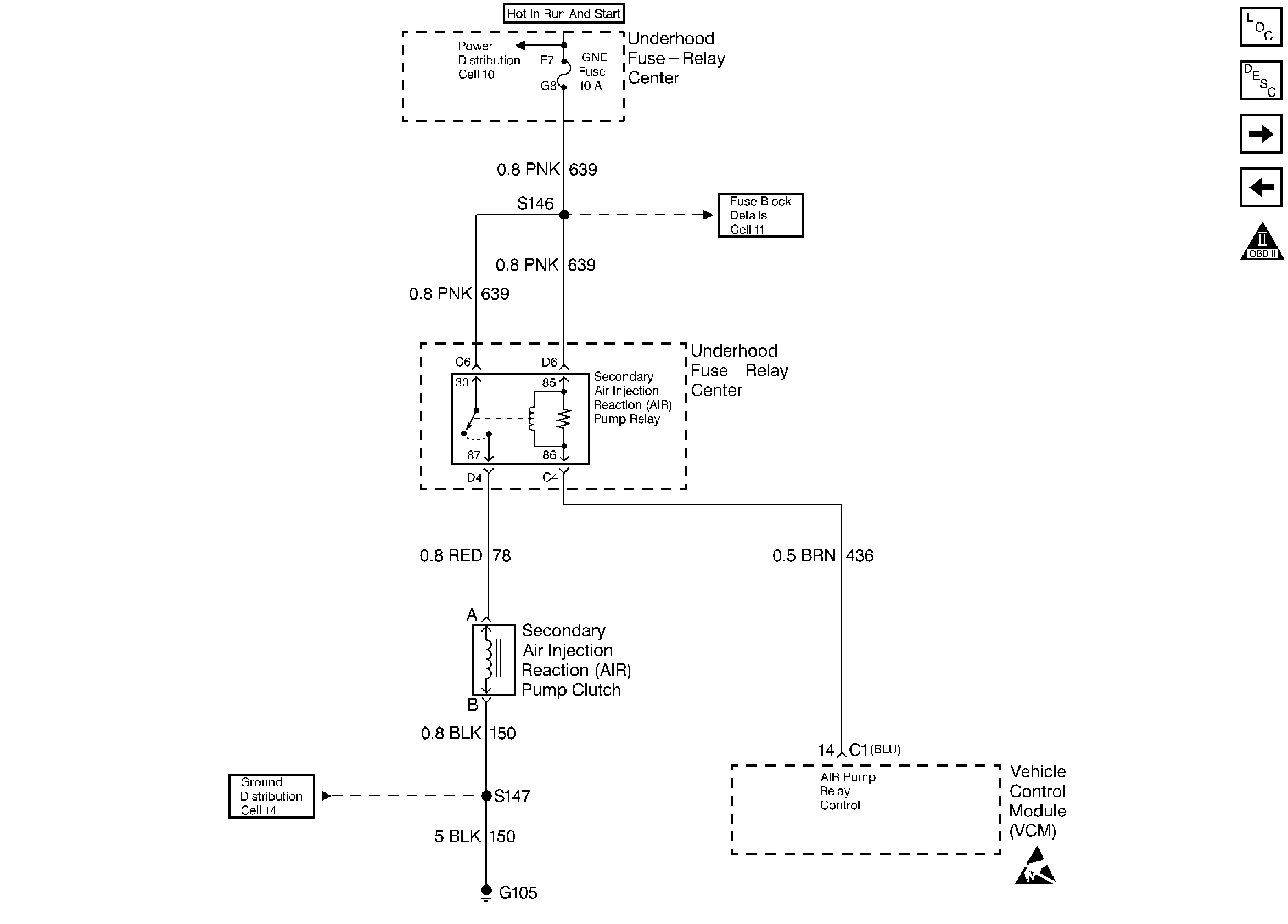
Circuit Description
A fused ignition voltage is supplied to the AIR relay. The VCM controls the AIR pump by grounding the AIR relay control circuit. This energizes the relay and supplies voltage to the AIR pump clutch. When the fuel system goes to the Closed Loop mode, the VCM opens the ground to the AIR control circuit.
Conditions for Setting the DTC
| • | No ECT sensor DTCs |
| • | No IAC sensor DTCs |
| • | No HO2S sensor DTCs |
| • | No Misfire DTCs |
| • | No MAP DTCs. |
| • | No Fuel Trim DTCs |
| • | No EVAP DTCs |
| • | Air/Fuel Ratio 14.7:1 |
| • | Engine Speed Above 550 RPM |
| • | Engine Load less than 50% |
| • | MAF less than 100 g/s |
| • | ECT between 75°C and 105°C |
| • | Decel Fuel Cutoff not active |
| • | Closed Loop for a period of greater than 15 seconds |
| • | System voltage greater than 10 volts |
| • | Power enrichment not active |
| • | A change in Short Term Fuel Trim less than 6% between Open and Closed Loop |
Action Taken When the DTC Sets
The VCM will turn ON the malfunction indicator lamp (MIL) after two consecutive test cycles with the fault active.
Conditions for Clearing the MIL/DTC
The VCM turns OFF the MIL after 3 consecutive driving trips without a fault condition present. A history DTC will clear if no fault conditions have been detected for 40 warm-up cycles (the coolant temperature has risen 22°C (40°F) from the start-up coolant temperature and the engine coolant temperature exceeds 71°C (160°F) during that same ignition cycle) or the scan tool clearing feature has been used.
Diagnostic Aids
An intermittent may be caused by a poor connection, rubbed through wire insulation, or a broken wire inside the insulation.
Check for the following conditions:
| • | Poor connection or damaged harness - Inspect the harness connectors for backed out terminals, improper mating, broken locks, improperly formed or damaged terminals, poor terminal to wire connection, and damaged harness. |
| • | Worn or loose AIR pump drive belt |
| • | Pinched, kinked, or restricted AIR pipes, hoses, or fittings |
Test Description
Number(s) below refer to the step number(s) on the Diagnostic Table.
-
This step will determine if the VCM is capable of controlling the AIR system.
-
This step will ensure that the VCM is capable of turning the AIR pump OFF.
-
This step will determine if there is a problem in the circuit between the AIR relay and AIR pump clutch ground.
-
This step will determine if the problem is in the AIR relay control circuit or the VCM.
Step | Action | Value(s) | Yes | No |
|---|---|---|---|---|
1 |
Important: Before clearing DTC(s) use the scan tool to record Freeze Frame and Failure Records for reference, as data will be lost when the Clear Info function is used. Was the Powertrain On-Board Diagnostic (OBD) System Check performed? | -- | ||
Does the Short Term Fuel Trim indicate a change of more than the specified value within 30 seconds? | 2 min 6 % | |||
3 | The DTC is intermittent. If no additional DTCs are stored, refer to Diagnostic Aids. If additional DTCs are stored, refer to those Table(s). Are any additional DTCs stored? | -- | Go to the Applicable DTC Table | |
4 |
Is the AIR pump clutch engaged? | -- | ||
Is the AIR pump clutch engaged? | -- | |||
6 |
Is the test light ON? | -- | ||
7 | With the AIR relay still disconnected, connect a test light to the AIR relay control circuit and B+. Is the test light ON? | -- | ||
8 |
Is the test light ON? | -- | ||
Connect a fused jumper to the AIR pump clutch control circuit and B+. Is the AIR pump clutch engaged? | -- | |||
10 | Connect a test light to the AIR pump clutch control circuit and ground. Is the test light ON? | -- | ||
11 | Check for an open in the AIR pump clutch control circuit. Was a problem found? | -- | ||
12 | Check for an open in the AIR pump ground circuit. Was a problem found? | -- | ||
13 | Check for an open in the AIR pump clutch coil. Was a problem found? | -- | ||
14 | Check for an open fuse in the AIR ignition feed circuit. Was a problem found? | -- | ||
15 | Check for an open in the AIR relay control circuit. Was a problem found? | -- | ||
16 | Check the terminal contact at the VCM for the AIR relay control circuit. Was a problem found? | -- | ||
Is the test light ON? | -- | |||
18 | Repair the short to ground in the ignition feed circuit to the AIR relay. Is the action complete? | -- | ||
19 | Repair the open in the ignition feed circuit to the AIR relay. Is the action complete? | -- | -- | |
20 | Replace the AIR relay. Is the action complete? | -- | -- | |
21 | Repair the short to ground in the AIR relay control circuit. Is the action complete? | -- | -- | |
22 | Repair the short to voltage on the AIR pump clutch control circuit. Is the action complete? | -- | -- | |
23 | Replace the VCM. Important: If the VCM is faulty, the new VCM must be programmed. Refer to VCM Replacement/Programming . Is the action complete? | -- | -- | |
24 | Repair as necessary. Is the action complete? | -- | -- | |
25 |
Does the airflow increase as the engine is accelerated? | -- | ||
26 |
Was a problem found? | -- | ||
27 | Replace the AIR pump. Refer to Secondary Air Injection System Description Is the action complete? | -- | -- | |
28 |
Does the scan tool indicate that this diagnostic Ran and Passed? | -- | ||
29 | Using the scan tool, select Capture Info, Review Info. Are any DTCs displayed that have not been diagnosed? | -- | Go to the Applicable DTC Table | System OK |
