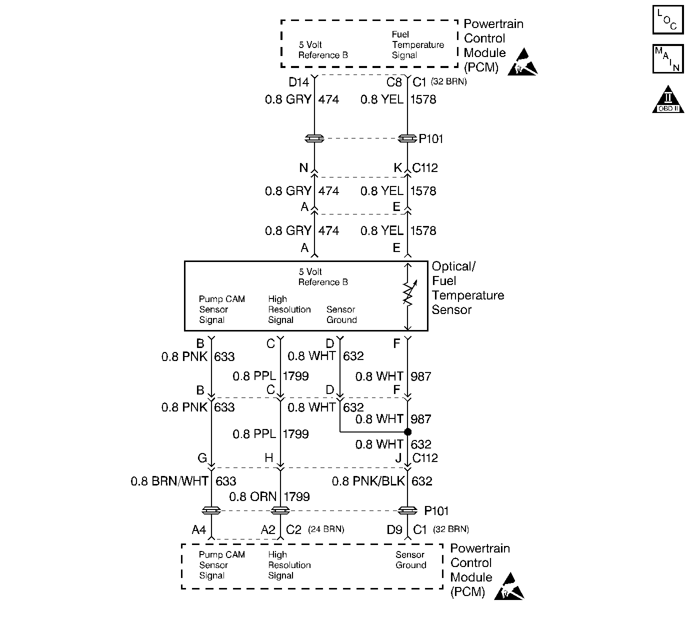
Circuit Description
The optical sensor provides a high resolution signal to the PCM by counting pulses on the sensor disk located in the injection pump. The high resolution is one of the most important inputs by the PCM for fuel control and timing. This test monitors the number of high resolution pulses which have been missed (not detected).Its based on a comparison between the number of pulses that were detected since the last pump cam pulse and the number of the pulses that should have occurred. This is a type A DTC.
Conditions for Setting the DTC
A number of High Resolution pulses (internal to PCM) per every 8 cam reference pulses.
Action Taken When the DTC Sets
Backup fuel.
Conditions for Clearing the MIL/DTC
| • | The PCM will turn the MIL off after three consecutive trips without a fault condition. |
| • | A History DTC will clear when forty consecutive warm-up cycles that the diagnostic does not fail (coolant temperature has risen 5°C (40°F) from start up coolant temperature and engine coolant temperature exceeds 71°C (160°F) that same ignition cycle. |
| • | Use of a Scan Tool |
Diagnostic Aids
When PCM is in backup fuel, fast idle and poor performance problems will exist. If P0251 is also stored, the snap shot mode on the scan tool should be used to properly identify fault. It is possible P0370 may set if the vehicle runs out of fuel.
Test Description
Number(s) below refer to the step number(s) on the Diagnostic Table.
-
This step will determine if the 5 volt reference is present.
-
This step checks the ground circuit.
-
This step determines if the problem is currently active by the scan tool displaying Last Test Failed. Do not proceed any further with this table if the scan tool does not display the term Last Test Failed. Duplicating the conditions in Freeze Frame and Failure Records can help create an active fault.
-
This step determines if a High Res signal is being sent to the PCM. Refer to the RPM vs Hertz table to compare the Hertz readings at different RPMs. Using Freeze Frame and Failure Records will help identify the RPM the problem occurs.
-
The PCM supplies 5 volts on the signal circuit. This step determines if that voltage is present, not present, or too much voltage is present..
-
This step determines if the signal circuit is shorted to 5V. A normal high res signal circuit will have 3-5mA. Any reading over 50mA indicates a short to 5V.
Step | Action | Value(s) | Yes | No |
|---|---|---|---|---|
1 |
Important: Before clearing any DTCs, use the scan tool Capture Info to save freeze frame and failure records for reference, as the scan tool loses data when using the Clear Info function. Was the Powertrain On-Board Diagnostic (OBD) System Check performed? | -- | ||
Is the voltage at specified value? | 4.8-5.2V | |||
Is the test light ON? | -- | |||
Does the scan tool display the term Last Test Failed? | -- | Go to Diagnostic Aids | ||
Important: The scan tool must display Last Test Failed (under DTC, Specific). This ensures the fault is active while performing this test. Referring to the RPM vs Hertz (Hz) table, does the Hertz reading in the table correspond (plus or minus 100 Hz) with the Hertz reading on the DMM at the designated RPM? | -- | |||
6 |
Is the resistance greater than the specified value? | 2.0 ohms | ||
7 |
Was the Optical sensor 5 volt reference circuit open or shorted to ground? | -- | ||
8 |
Was a repair performed? | -- | ||
9 | Check the Optical sensor 5 volt reference circuit for a proper connection at the PCM and replace the terminal if necessary. Did the terminal require replacement? | -- | ||
Is the voltage within the specified value? | 4.8-5.2V | |||
11 | Is the voltage greater than the specified value? | 4.8-5.2V | ||
12 | Repair the short to battery/ignition voltage on the high resolution signal circuit. Is the action complete? | -- | -- | |
13 |
Was a repair made? | -- | ||
With a DMM J 39200 set to the mA scale, measure the current between the High Res signal circuit and the ground circuit at the Optical/Fuel temperature sensor electrical connector. Is the current less than the specified value? | 50mA | |||
15 | Repair the short to reference voltage on the high resolution signal circuit. Is the action complete? | -- | -- | |
16 |
Was a problem found? | -- | ||
17 |
Was a problem found? | -- | ||
18 | Replace the electrical filter harness. Is the action complete? | -- | -- | |
19 | Replace the injection pump. Refer to Fuel Injection Pump Replacement . Important: The new injection pump must be timed. Refer to Checking/Adjust Injection Timing . Is the action complete? | -- | -- | |
20 | Replace the PCM. Important: The new PCM must be programmed. Refer to Powertrain Control Module Replacement/Programming . Is the action complete? | -- | -- | |
21 |
Does the Scan Tool indicate the diagnostic Passed? | -- | ||
22 | Does the Scan Tool display any additional undiagnosed DTCs? | -- | Go to the Applicable DTC Table | System OK |
