The Magna Powertrain (MP) model 3023/3024 RPO NQH transfer case is a 2 speed automatic, active transfer case (ATC). The MP 3023/3024 ATC provides 5 modes, Auto 4WD, 4HI, 4LO, 2HI and NEUTRAL. The Auto 4WD position allows the capability of an active transfer case, which provides the benefits of on-demand torque biasing wet clutch and easy vehicle tuning through software calibrations. The software calibrations allow more features such as flexible adapt ready position and clutch preload torque levels. The technology allows for vehicle speed dependent clutch torque levels to enhance the performance of the system. For example, the system is calibrated to provide 0-6.78 N·m (0-5 lb ft) of clutch torque during low speed, low engine torque operation, and predetermined higher torque for 40 km/h (25 mph) and greater. This prevents crow-hop and binding at low speeds and provides higher torque biases at higher vehicle speeds, in order to enhance stability.
Transfer Case Shift Control Switch
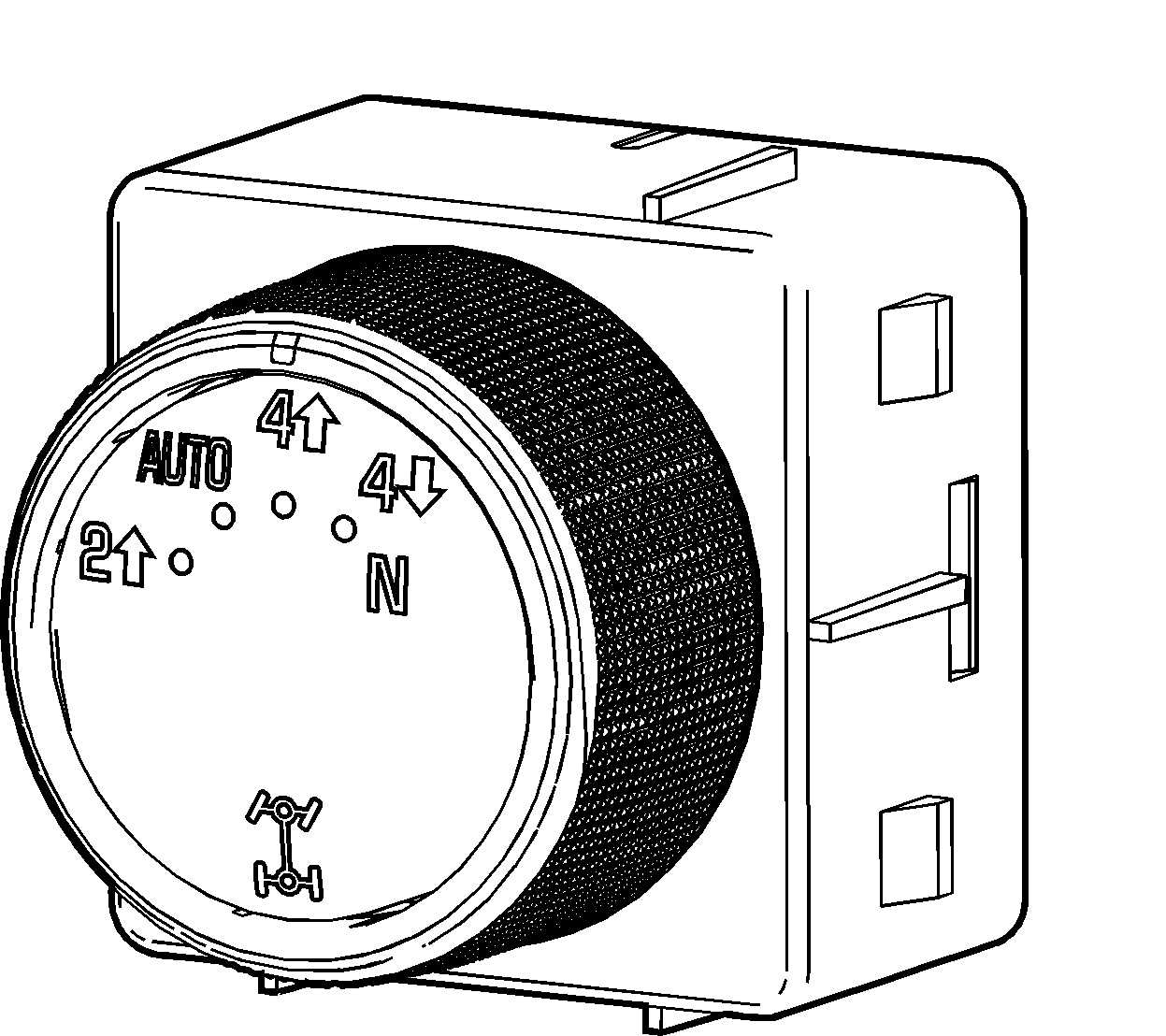
The MP 3023/3024 ATC transfer case features a 4 mode shift control switch located on the instrument panel. When the ignition key is in the RUN position, the transfer case shift control module monitors the transfer case shift control switch to determine if the driver desires a new mode/range position. At a turn of the transfer case shift control switch, the lamp of the new desired position will begin flashing to inform the driver that the transfer case shift control module has received the request for a new mode/range position. The lamp continues to flash until all shifting criteria has been met and the new mode/range position has been reached, or has been engaged. Once the new mode/range position is fully active, the switch indicator lamp for the new position will remain ON constantly.
During normal driving situations, the transfer case can operate in the Auto 4WD mode. In the Auto 4WD mode, the transfer case shift control module monitors rear wheel slip speed, based on the inputs from the wheel speed sensors. When the vehicle experiences a rear wheel slip condition, the transfer case shift control module sends a pulse width modulated (PWM) signal to an electronic motor, which is the transfer case 2/4 wheel drive actuator assembly. This actuator rotates the transfer case control actuator shaft, applying a clutch. The clutch is designed to deliver a variable amount of torque, normally delivered to the rear wheels, and transfers it to the front wheels. Torque is ramped up to the front wheels until the front wheel speed sensors matches that of the rear speed sensors. Torque is ramped down to the front wheels. The process would repeat if rear wheel slip is detected again.
The MP 3023/3024 ATC transfer case has the added feature of also providing the driver with 4 manual mode/range positions:
| • | 4HI - 4 Wheel Drive high range |
| • | 2HI - 2 Wheel Drive high range |
| • | 4LO - 4 Wheel Drive low range, 2.68:1 gear ratio reduction |
| • | Neutral |
The driver may choose to select any of these mode/range positions while driving the vehicle. However, the transfer case will not allow a shift into or out of 4LO unless the following criteria has been met:
| • | The ignition switch is in RUN. |
| • | The automatic transmission is in NEUTRAL. |
| • | The vehicle speed is below 5 km/h (3 mph). |
This transfer case also has a NEUTRAL position. A shift to the NEUTRAL position allows the vehicle to be towed without rotating the transmission output shaft. In the NEUTRAL position, the rear propeller shaft rotates the transfer case rear output shaft, in turn rotating the oil pump, thus providing constant lubrication during towing. NEUTRAL position may be obtained only if the following criteria has been met:
| • | The ignition switch is in RUN. |
| • | The automatic transmission is in NEUTRAL. |
| • | The vehicle speed is below 5 km/h (3 mph). |
| • | The transfer case is in 2HI mode. |
Once these conditions have been met, turn the rotary switch clockwise past 4 low and hold for 10 seconds. When the system completes the shift to NEUTRAL, the red NEUTRAL lamp will illuminate.
The NQH transfer case is available in 2 variations, depending on the engine and transmission configurations. The variations allow the transfer case to handle torque loads. When servicing the transfer case, it is important to understand which variation is being serviced because of the difference in parts.
Model | Transmission | Input Shaft | Output Shaft | Chain Size | Chain Series | Hi/Low Planetary | Application |
|---|---|---|---|---|---|---|---|
MP 3023 ATC Light Duty (LD) | M30 - 4L60-E | 27T Spline | 32T Spline | 7/16x1.25 in | 9600 Series Rocker Pin Chain | 3 Pinion | K1 |
MP 3023 ATC Light Duty (LD) | M99 - Hybrid | 32T Spline | 32T Spline | 7/16x1.25 in | 9600 Series Rocker Pin Chain | 3 Pinion | K1 |
MP 3024 ATC Heavy Duty (HD) | MYD - 6L90 | 29T Spline | 31T Spline | 7/16x1.5 in | 9600 Series Rocker Pin Chain | 5 Pinion | K2 |
Additional differences in these models are listed below:
MP 3023 ATC with 27T Input Spline
| • | The high/low clutch has bias pointing engagement teeth. The leading edges of the teeth are not symmetric. |
| • | The rear output shaft rear bearing retaining rings are larger than the MP 3023 ATC with 32T Input Spline but smaller than the MP 3024. The inner diameter of the ring groove at the rear output shaft measures 37.5 mm (1.476 in). |
| • | The rear output shaft bearing assembly inner diameter measures 40 mm (1.575 in) the width measures 18 mm (0.709 in). |
| • | The rear output shaft bearing assembly surface on the rear output shaft measures 40 mm (1.575 in). |
MP 3023 ATC with 32T Input Spline
| • | The high/low clutch has neutral pointing engagement teeth. The leading edges of the teeth are symmetric. |
| • | The speed reluctor wheel profile thickness is thinner than the MP 3023 ATC with 27T input spline and the MP 3024, measuring 25.8 mm (1.016 in) thick. |
| • | There is no snap ring between the speed reluctor wheel and the rear output shaft rear bearing assembly. |
| • | There is no snap ring groove in the rear output shaft between the speed reluctor wheel and the rear output shaft rear bearing assembly. |
| • | The rear output shaft rear bearing retaining ring is smaller than the MP 3023 ATC with 27T input spline and the MP 3024. The inner diameter of the ring groove at the rear output shaft measures 33 mm (1.299 in). |
| • | The rear output shaft bearing assembly inner diameter measures 35 mm (1.378 in) the width measures 23 mm (0.906 in). |
| • | The rear output shaft bearing assembly surface on the rear output shaft measures 35 mm (1.378 in). |
| • | There is an additional harness bracket. |
MP 3023 ATC, Common to LD
| • | The input shaft pilot bearing assembly is smaller than the MP 3024 ATC in order to accommodate the smaller rear output shaft. The outer diameter measures 38.1 mm (1.5 in). |
| • | The rear output shaft is smaller than the MP 3024 ATC. |
| • | The front output shaft drive sprocket is 27.2 mm (1.071 in) wide. |
| • | The front output shaft driven sprocket is 29.4 mm (1.157 in) wide. |
| • | The rear output shaft seal is smaller than the MP 3024 ATC. The inner lip diameter measures 46.1 mm (1.815 in). |
| • | The rear output shaft bushing is smaller than the MP 3024 ATC. The inner diameter measures 48 mm (1.890 in). |
| • | The rear case half has smaller bores than the MP 3024 ATC in order to accommodate the rear output shaft seal and the rear output shaft bushing. |
| • | The control lever is thinner than the MP 3024 ATC, measuring 9.5 mm (0.374 in) between the bearing surfaces. |
| • | The control actuator lever is thinner than the MP 3024 ATC, measuring 9.5 mm (0.374 in) between the bearing surfaces. |
| • | The control actuator lever balls are larger than the MP 3024 ATC, measuring 13 mm (0.512 in) in diameter. |
| • | The control actuator lever washer is thinner than the MP 3024 ATC, measuring 1 mm (0.039 in). |
MP 3024 ATC
| • | The input shaft pilot bearing assembly is larger than the MP 3023 ATC in order to accommodate the larger rear output shaft. The outer diameter measures 41.275 mm (1.625 in). |
| • | An input shaft pilot bearing retaining ring is used. |
| • | The high/low clutch has neutral pointing engagement teeth. The leading edges of the teeth are symmetric. |
| • | The rear output shaft is larger than the MP 3023 ATC. |
| • | The front output shaft drive sprocket is 33.5 mm (1.319 in) wide. |
| • | The front output shaft driven sprocket is 35.5 mm (1.398 in) wide. |
| • | The rear output shaft rear bearing retaining rings are larger than the MP 3023 ATC. The inner diameter of the ring groove at the rear output shaft measures 38.5 mm (1.516 in). |
| • | The rear output shaft rear bearing assembly inner diameter measures 41 mm (1.614 in). The width measures 18 mm (0.709 in). |
| • | The rear output shaft bearing assembly surface on the rear output shaft measures 41 mm (1.614 in). |
| • | The rear output shaft seal is larger than the MP 3023 ATC. The inner lip diameter measures 53.8 mm (2.118 in). |
| • | The rear output shaft bushing is larger than the MP 3023 ATC. The inner diameter measures 56.08 mm (2.208 in). |
| • | The rear case half has larger bores than the MP 3023 ATC in order to accommodate the rear output shaft seal and the rear output shaft bushing. |
| • | The control lever is thicker than the MP 3023 ATC, measuring 10.5 mm (0.413 in) between the bearing surfaces. |
| • | The control actuator lever is thicker than the MP 3023 ATC, measuring 10.5 mm (0.413 in) between the bearing surfaces. |
| • | The control actuator lever balls are smaller than the MP 3023 ATC, measuring 10 mm (0.394 in) in diameter. |
| • | The control actuator lever washer is thicker than the MP 3023 ATC, measuring 2.5 mm (0.098 in). |
2WD Mode Power Flow
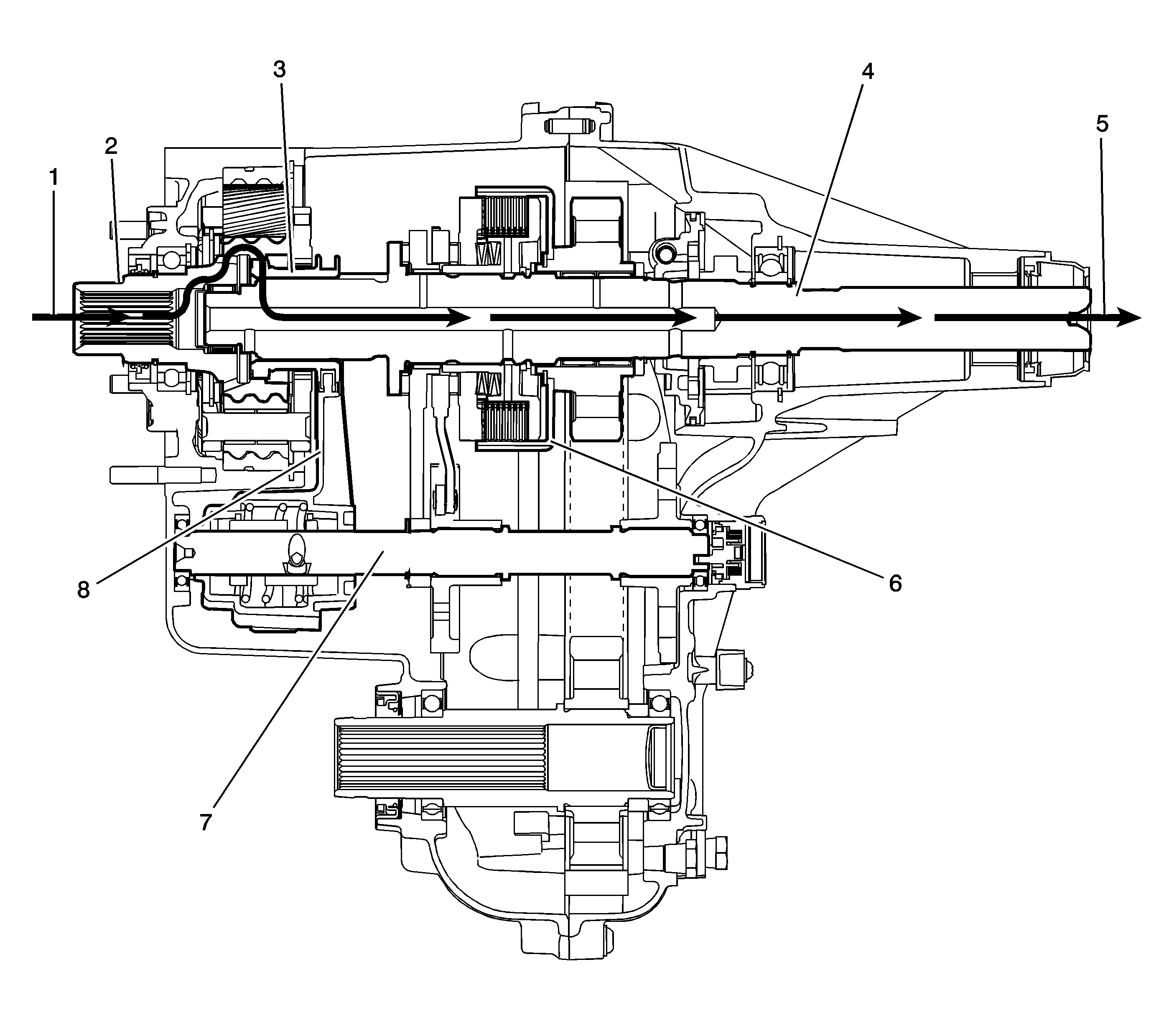
When the MP 3023/3024 ATC is in the 2WD mode, the power flows from the transmission (1) to the input shaft (2). The input shaft (2) is connected to the rear output shaft (4) by the high/low clutch (3). The high/low clutch (3) outer teeth are engaged with the input shaft (2) inner, high-speed position teeth. At the same time the high/low clutch is slip splined to the rear output shaft (4). The rear output shaft (4) delivers the power flow to the rear propshaft (5). The position of the control actuator shaft (7) allows no clutch (6) engagement. The high/low range shift fork (8), is in the high-speed position on the control actuator shaft (7).
4HI Mode Power Flow
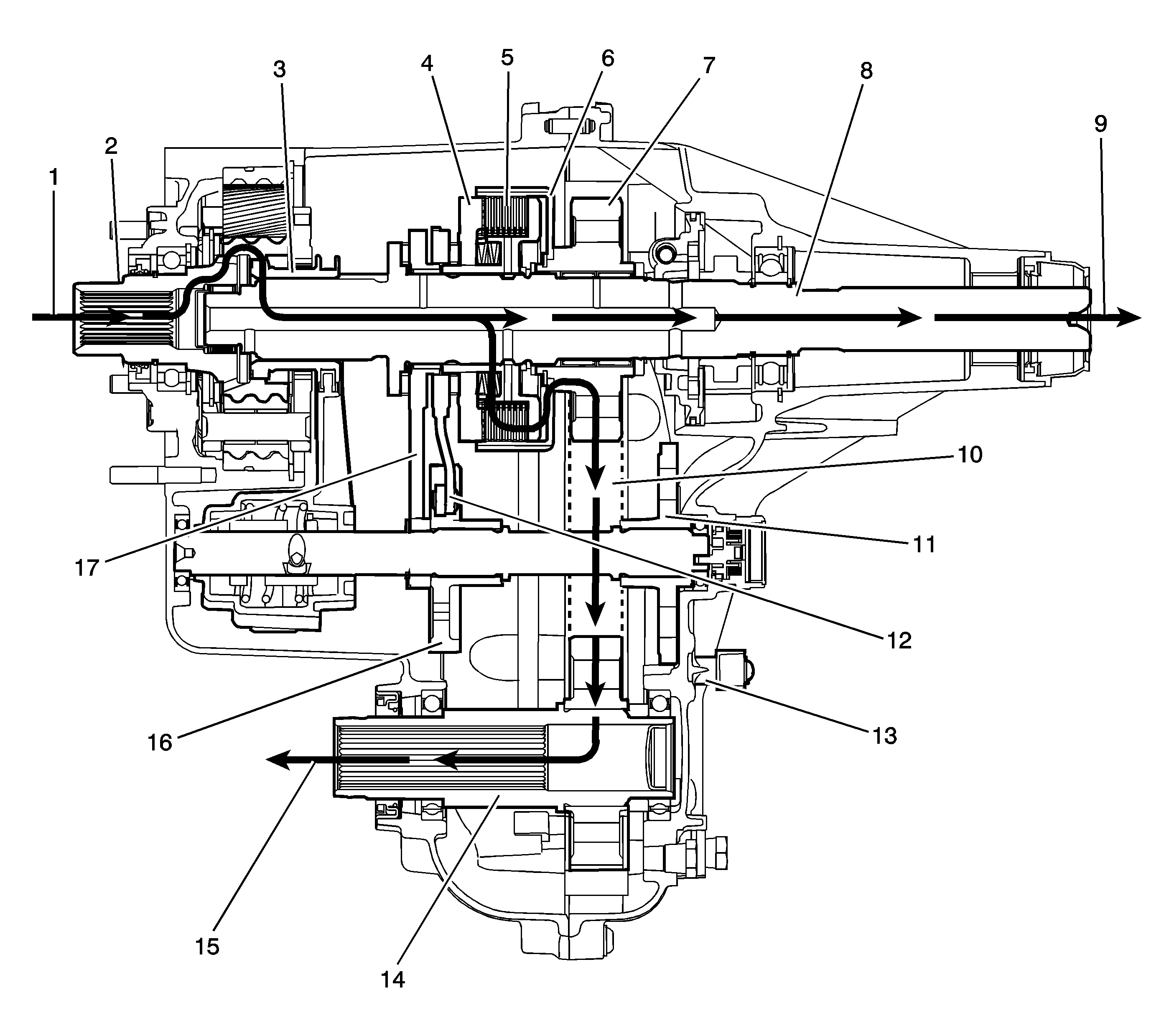
In the 4HI mode, the power flow to the rear propshaft (9) is the same as it is in the 2WD mode. To deliver power flow to the front propshaft (15) during the 4HI position, the transfer case control module commands the 2/4 wheel drive actuator assembly (13) to apply the clutch to a calibrated torque. The 2/4 wheel drive actuator assembly (13) turns the control actuator shaft. A brake in the 2/4 wheel drive actuator assembly (13) holds the control actuator shaft in the full clutch position. The control actuator shaft is cam designed and the cam action moves the control actuator lever (12). The control actuator lever (12) pivots against the control lever (17) and moves toward the clutch pressure plate (4), to engage the clutch (5). As more pressure is applied to the clutch pressure plate (4), the clutch discs (5) are compressed. Using inner clutch discs, which are engaged with the clutch hub, and the outer clutch discs, which are engaged with the clutch housing (6), the power flow is delivered to the clutch housing (6). The clutch hub is splined to the rear output shaft (8), and the clutch housing (6) rotates on a needle bearing on the rear output shaft (8). The chain drive sprocket (7) is splined to the clutch housing (6). The power flows from the drive sprocket (7), through the chain (10), to the chain driven sprocket. The driven sprocket is splined to the front output shaft (14). The power flow is delivered to the front propshaft (15) through the front output shaft (14).
During the Auto 4WD mode, the power flow is the same as it is in the 4HI mode. Except, during the Auto 4WD mode, the 2/4 wheel drive actuator assembly (13) rotates the control actuator shaft to the correct torque level positions. Rotating the control actuator shaft to the various positions changes the clutch torque level. When a difference of front wheel speed to rear wheel speed is recognized, the transfer case control modules command for more, or less clutch torque.
4LO Mode Power Flow
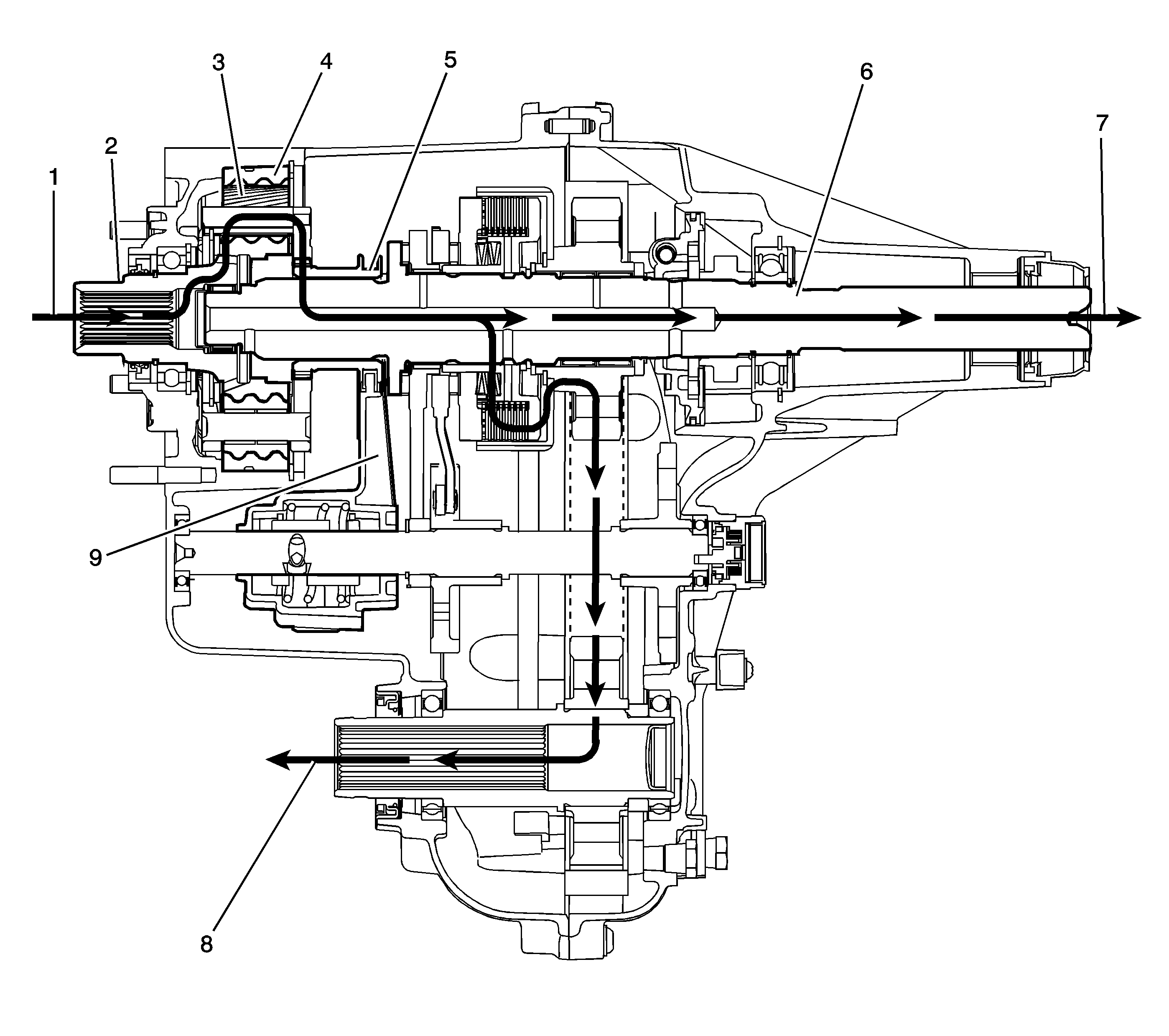
When shifting the transfer case to the 4LO mode, it commands the 2/4 wheel drive actuator assembly to turn the control actuator shaft, to move the high/low shift fork (9). The shift fork (9) moves the high/low clutch (5), which is slip splined on the rear output shaft (6) toward the rear of the transfer case. The high/low clutch (5) outer teeth disengage from the input shaft (2) inner teeth. The high/low clutch (5) outer teeth then engage in the planetary carrier teeth. The power flow is now from the input shaft (2) planetary teeth to the planetary gears (3) in the carrier. Rotating the planetary gears (3), which are engaged in the high/low internal gear (4), the planetary carrier rotates. The planetary carrier engaged to the high/low clutch (5), drives the rear output shaft (6), providing a 2.68:1 reduction to the speed of the rear output shaft (6). The power flow to the front propshaft (8) is the same as it is in the 4HI.
NEUTRAL Mode Power Flow
Shifting to the NEUTRAL position, the high/low clutch is centered between the input shaft and the high/low planetary carrier. The high/low clutch is not engaged with either the input shaft or the high/low planetary carrier teeth.
Service 4WD Indicator
The Service 4WD indicator is an integral part of the cluster and cannot be serviced separately. This lamp is used to inform the driver of the vehicle that a transfer case system malfunctioned. The Service 4WD indicator is controlled by the transfer case shift control module via Class 2.
Transfer Case Two/Four Wheel Drive Incremental Sensor
The incremental sensor is mounted to the transfer case actuator assembly and is replaced as an assembly. The incremental sensor converts the shift detent lever shaft position, representing a mode or range, into an electrical signal input to the transfer case shift control module. The module detects what position the transfer case is in by monitoring the voltage returned on the incremental encoder impulse signal circuit. This voltage translates into AUTO 4WD, 2HI, 4HI, NEUTRAL, and 4LO or in transition between gears.
Transfer Case Two/Four Wheel Drive Actuator Assembly
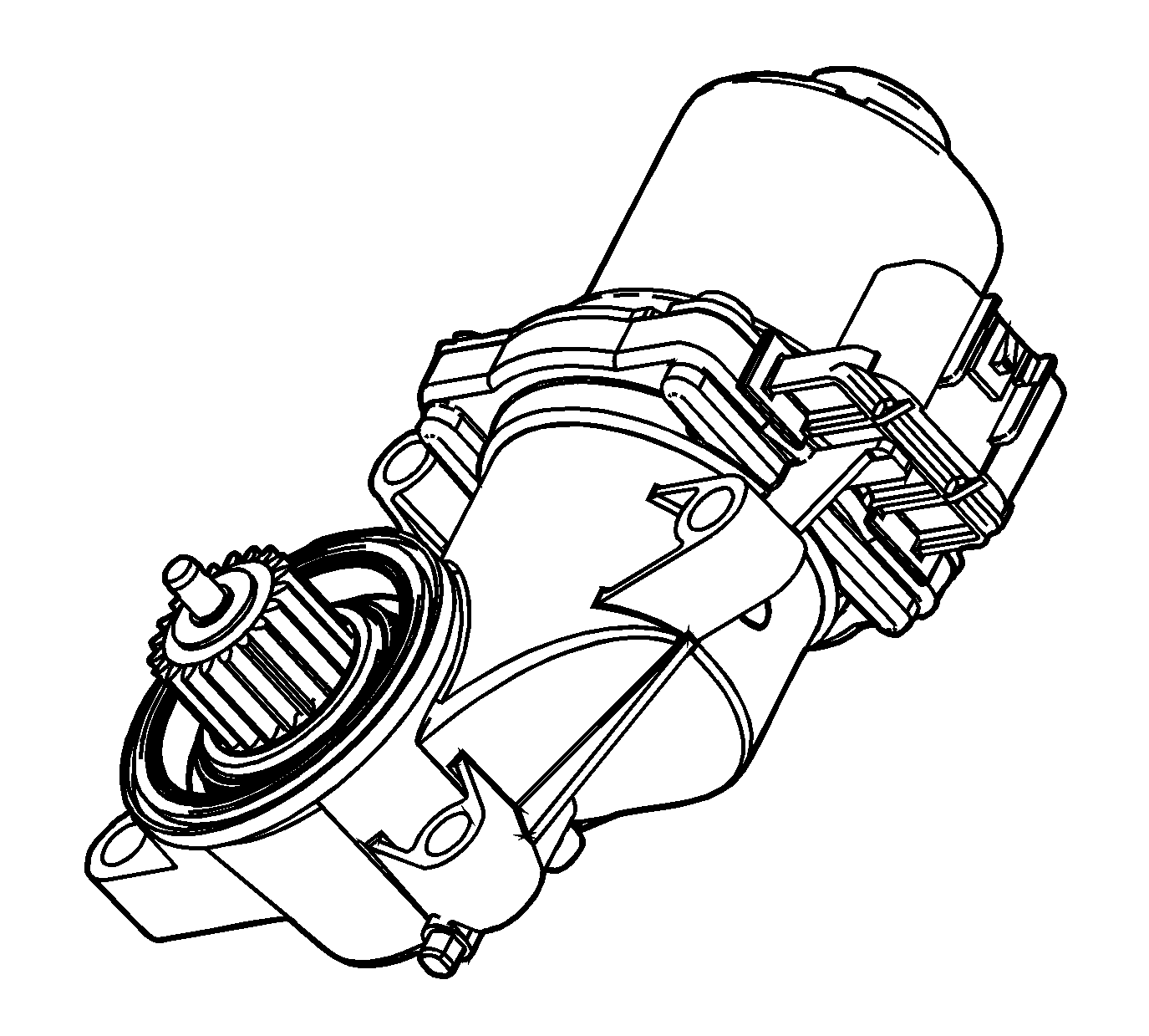
The transfer case two/four wheel drive actuator assembly consists of a permanent magnet DC motor and gear reduction assembly. It is located on the left hand side, driver's side, of the transfer case. When activated, it turns the shift detent lever shaft of the transfer case, clockwise or counterclockwise, to shift the transfer case. The motor/encoder is controlled with a PWM signal by the transfer case shift control module. This circuit consists of a driver on both the Motor A and Motor B circuits. The encoder motor is bi-directional in order to allow the motor to shift the transfer case from 2HI or 4HI to NEUTRAL and 4LO positions.
Transfer Case Actuator Shaft Position Sensor Assembly
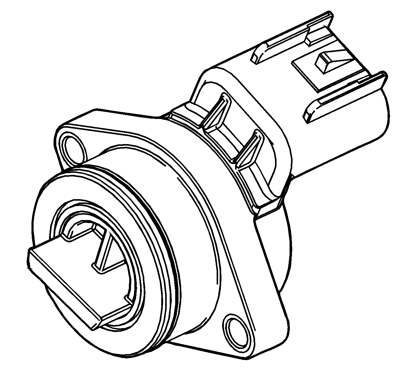
This sensor works in conjunction with the incremental sensor and shows transfer case position in degrees.
Transfer Case Motor Lock
The transfer case motor lock is used to provide a 2HI, 4HI, and 4LO lock-up feature. When the lock circuit is energized, the transfer case encoder motor is allowed to turn. When the transfer case is placed 2HI, 4HI, or 4LO the motor lock circuit is de-energized and the lock is applied. This assures that the transfer case remains in the current gear position until a new gear position is requested. When AUTO 4WD is selected, the motor lock remains applied until an adaptive mode, torque being applied to the front propshaft, is required. During an adaptive mode the motor lock circuit is energized and the motor lock is released, enabling the encoder motor to turn and apply or release torque at the front propshaft.
Transfer Case Shift Control Module
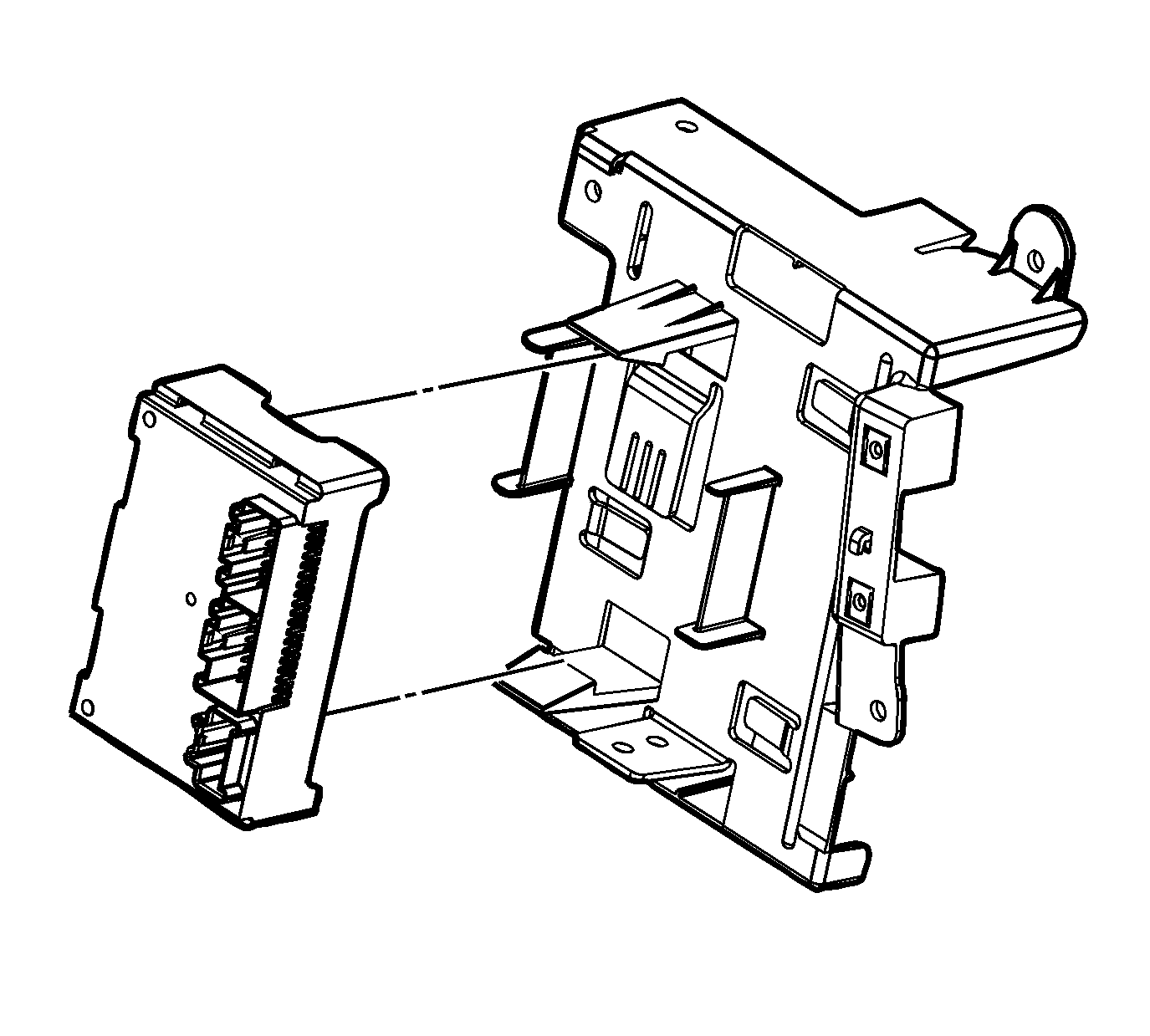
The transfer case shift control module uses the vehicle identification number (VIN) information for calculations that are required for the different calibrations used based on axle ratio, transmission, tire size, and engine. The system does not know which calibration to use without this information. When the vehicle is in the AUTO 4WD mode, the transfer case shift control module monitors the speed of the front and rear propshaft, in order to detect wheel slippage. When wheel slippage is detected, the module applies a clutch pack contained inside the transfer case. This clutch pack is used to lock-in and apply the front propshaft, transferring torque to the front wheels. The clutch pack is applied by a motor/encoder assembly. When slip is no longer detected by the transfer case shift control module, the clutch is no longer applied.
Vehicle Speed Sensor (VSS)
There is a VSS mounted to the transfer case on the rear output shaft. The VSS is a PM generator. The PM generator produces a AC voltage. The AC voltage and frequency increases as speed increases. The VSS is an input to the powertrain control module (PCM). The PCM sends this information to the transfer case shift control module via the GM LAN serial data bus.
