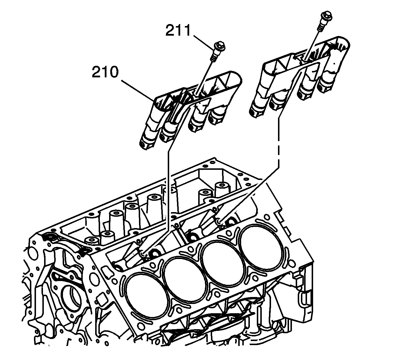
Valve Lifter Replacement Except RPOs LC9, LH6, LMG, LME, LY5,
Removal Procedure
- Remove the cylinder head and gasket. Refer to Cylinder Head Replacement - Left Side or Cylinder Head Replacement - Right Side.
- Remove the valve lifter guide bolts (211).
- Remove the valve lifter guides (210) with the lifters. Note the installed position of the guides. The notched area of the guides is to align with the locating tab on the engine block.
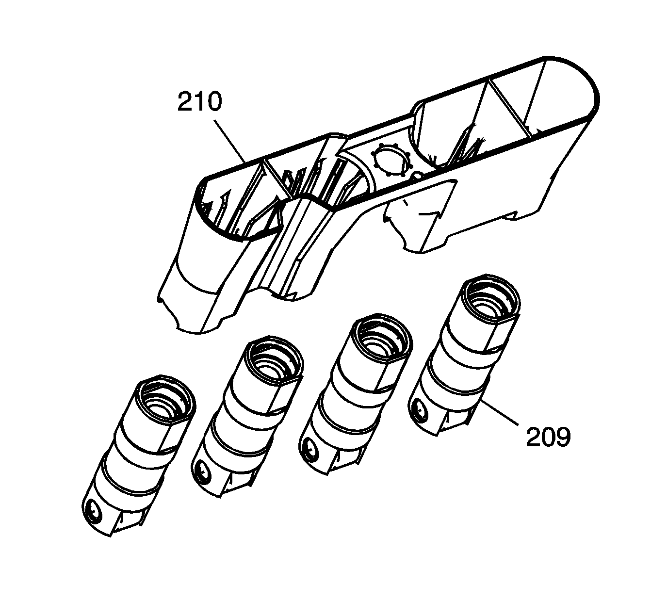
- Remove the valve lifters (209) from the guide (210).
- Organize or mark the components so that they can be installed in the same location from which they were removed, if required.
- Clean and inspect the valve lifters, if required. Refer to Valve Lifter and Guide Cleaning and Inspection.
Installation Procedure
Important: When reusing valve lifters, install the lifters to their original locations.
- Lubricate the valve lifters (209) and engine block valve lifter bores with clean engine oil.
- Insert the valve lifters into the lifter guides (210). Align the flat area on the top of the lifter with the flat area in the lifter guide bore. Push the lifter completely into the guide bore.
- Install the valve lifters and guide (210) to the engine block.
- Install the valve lifter guide bolts.
- Install the cylinder head and gasket. Refer to Cylinder Head Replacement - Left Side or Cylinder Head Replacement - Right Side.
Notice: Refer to Fastener Notice in the Preface section.
Tighten
Tighten the bolt to 12 N·m (106 lb in).
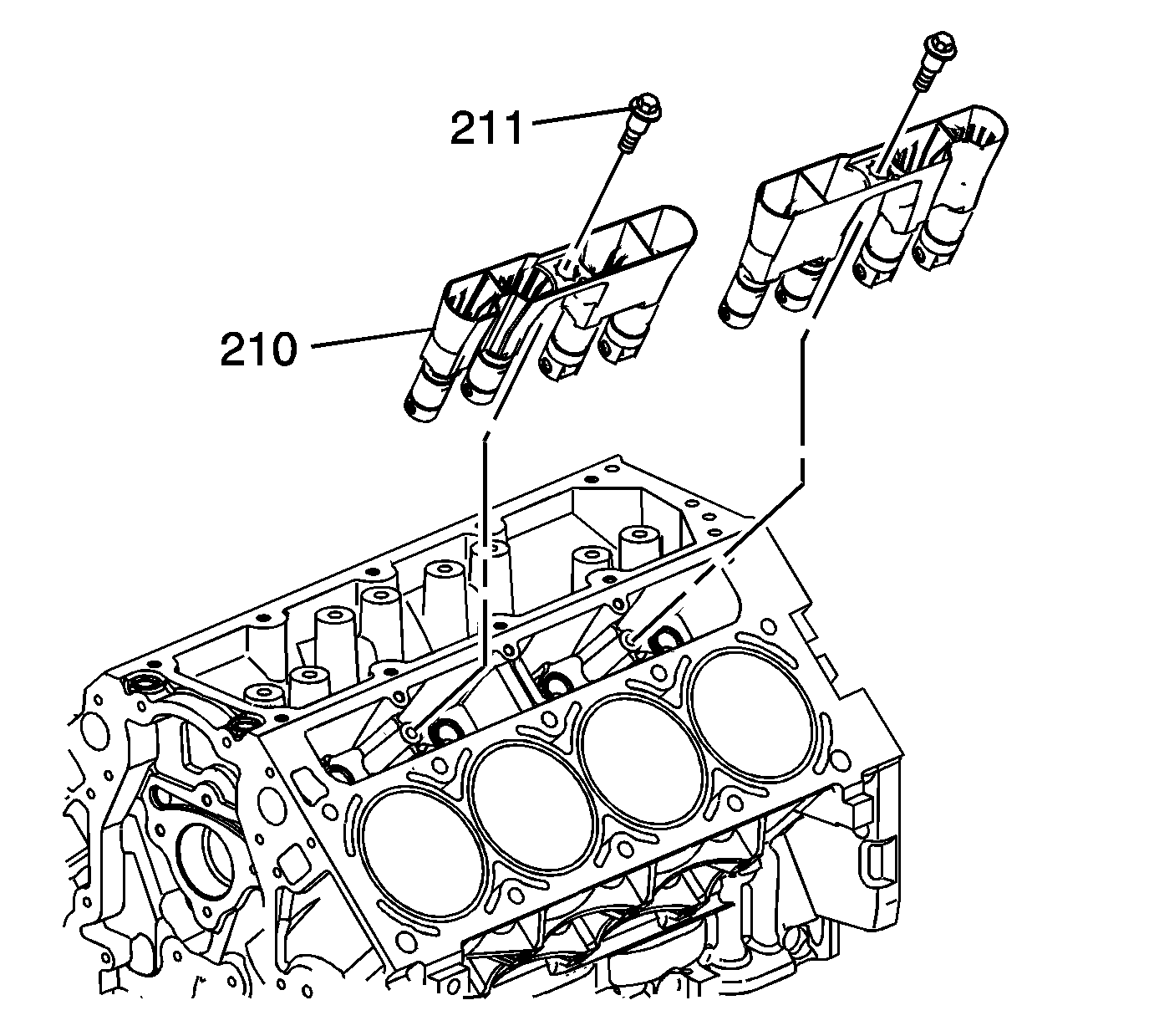
Valve Lifter Replacement RPOs LC9, LH6, LMG, LY5, L76
Removal Procedure
- Remove the cylinder head and gasket. Refer to Cylinder Head Replacement - Left Side or Cylinder Head Replacement - Right Side.
- Remove the valve lifter guide bolts (211).
- Remove the valve lifter guides (210) with the lifters. Note the installed position of the guides. The notched area of the guides is to align with the locating tab on the engine block.
- Remove the valve lifters (209, 219) from the guide (210).
- Organize or mark the components so that they can be installed in the same location from which they were removed, if required.
- Clean and inspect the valve lifters, if required. Refer to Valve Lifter and Guide Cleaning and Inspection.
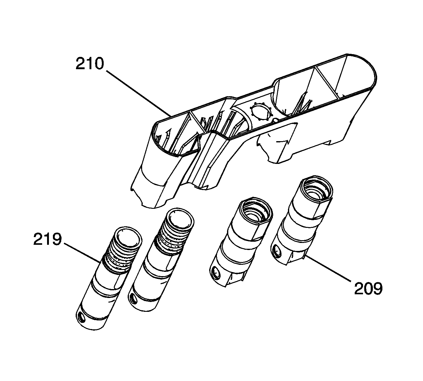
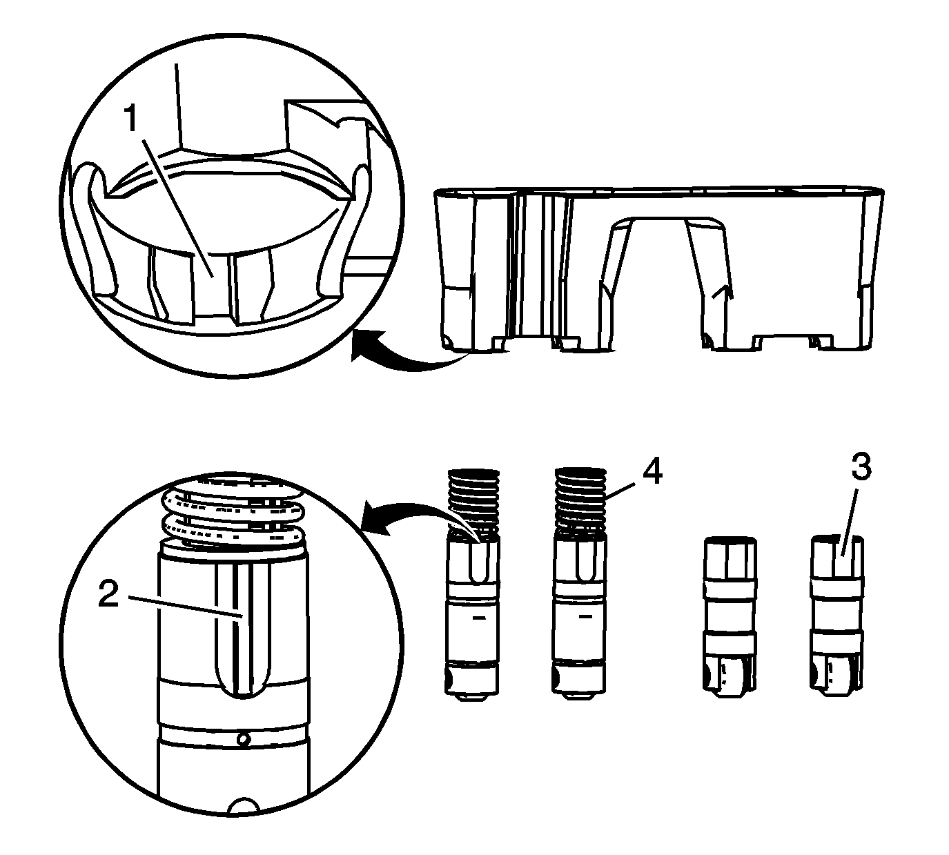
Important: The active fuel management lifters are installed into the guide by aligning the notched area of the guide (1) with the raised surface on the side of the lifter (2).
Installation Procedure
Important:
• When reusing valve lifters, install the lifters to their original locations. • Each of the 4 valve guide assemblies will contain 2 active fuel management valve lifters and 2 non active fuel management valve lifters. • With the lifters and guides properly installed, cylinders 1, 4, 6, and 7 lifter bores will each contain 2 active fuel management valve lifters.
- Lubricate the valve lifters (209, 219) and engine block valve lifter bores with clean engine oil.
- Insert the valve lifters into the lifter guides.
- Install the valve lifters and guide (210) to the engine block.
- Install the valve lifter guide bolts (211).
- Install the cylinder head and gasket. Refer to Cylinder Head Replacement - Left Side or Cylinder Head Replacement - Right Side.
| • | Align the flat area (3) on the top of the non active fuel management lifter with the flat area in the lifter guide bore. Push the lifter completely into the guide bore. |
| • | The active fuel management lifters are to be installed into the guide, with the notch in the guide (1) aligned with the raised area (2) of the lifter. |
Notice: Refer to Fastener Notice in the Preface section.
Tighten
Tighten the bolt to 12 N·m (106 lb in).
