Removal Procedure
- Drain the engine coolant and the engine block. Refer to Cooling System Draining and Filling in Engine Cooling.
- Raise the vehicle. Refer to Lifting and Jacking the Vehicle in General Information.
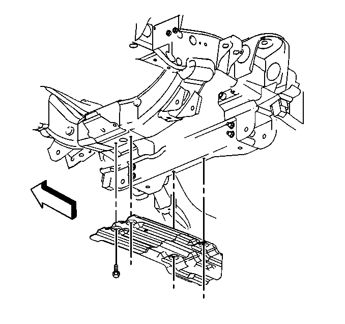
- Remove the oil pan skid plate. (2WD shown).
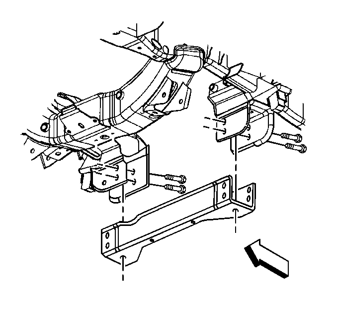
- Remove the crossbar (2WD shown).
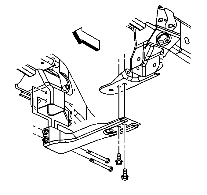
- Remove the crossbar (4WD shown).
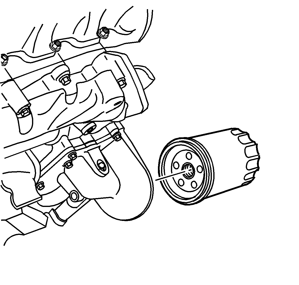
- Remove the oil filter.
- Remove the left front tire. Refer to Tire and Wheel Removal and Installation in Tires and Wheels.
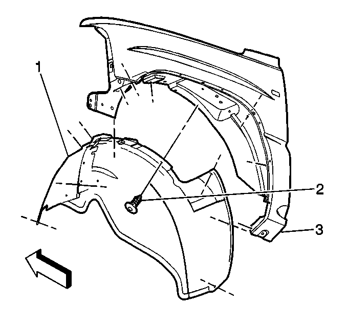
- Remove the left front fender wheelhouse inner panel (1).
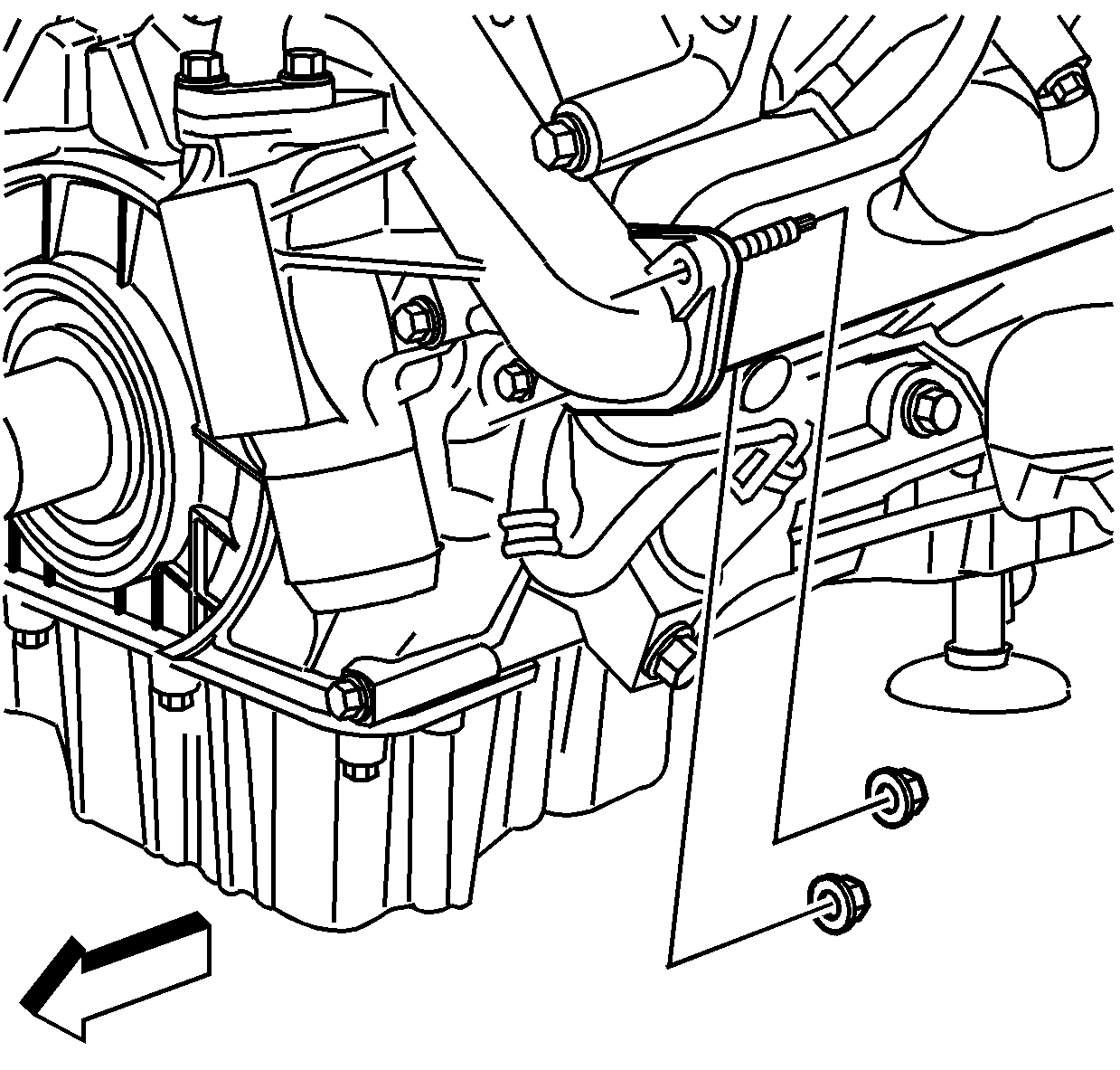
- Remove the 2 water pump outlet pipe nuts from water pump.
- Remove the engine wiring harness retainer from the inner stud.
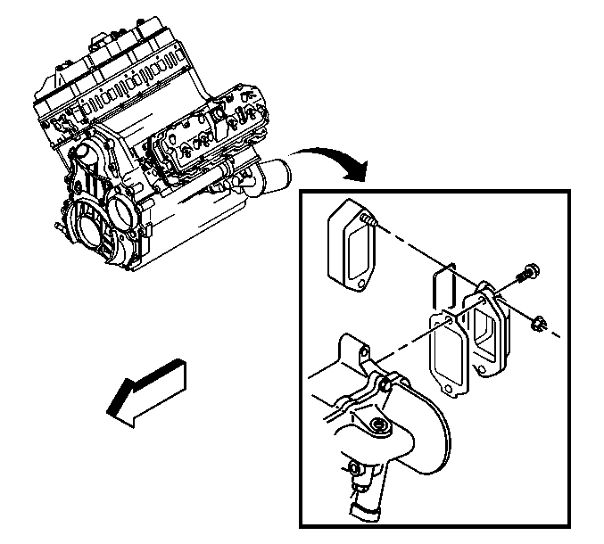
- Remove the 2 nuts for the coolant duct from the engine flywheel housing.
- Remove the 2 bolts for the coolant duct from the oil filter adapter and the oil cooler assembly.
- Remove the coolant duct.
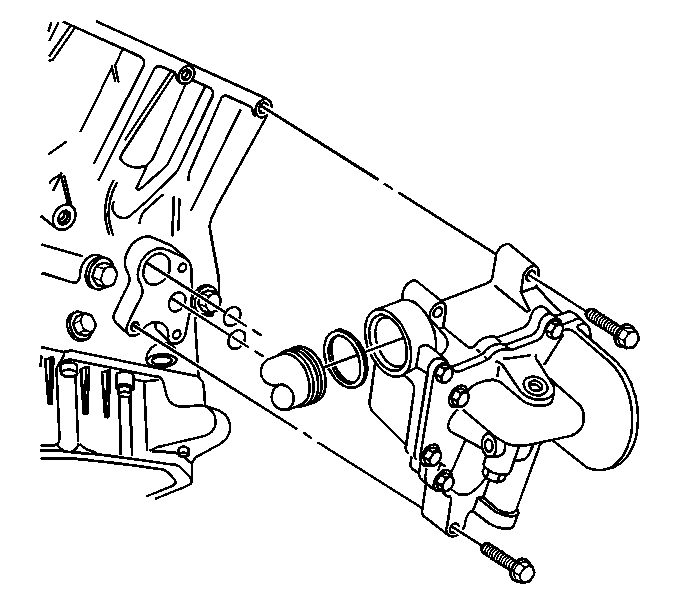
- Remove the oil filter adapter and 5 oil cooler assembly bolts.
- Remove the oil filter adapter and oil cooler assembly with the water pump outlet pipe.
- Remove the oil filter adapter and oil cooler assembly 2 O-ring seals.
- Remove the water pump outlet pipe from the oil cooler assembly.
- Remove the water pump outlet pipe O-ring.
Inspection and Repair
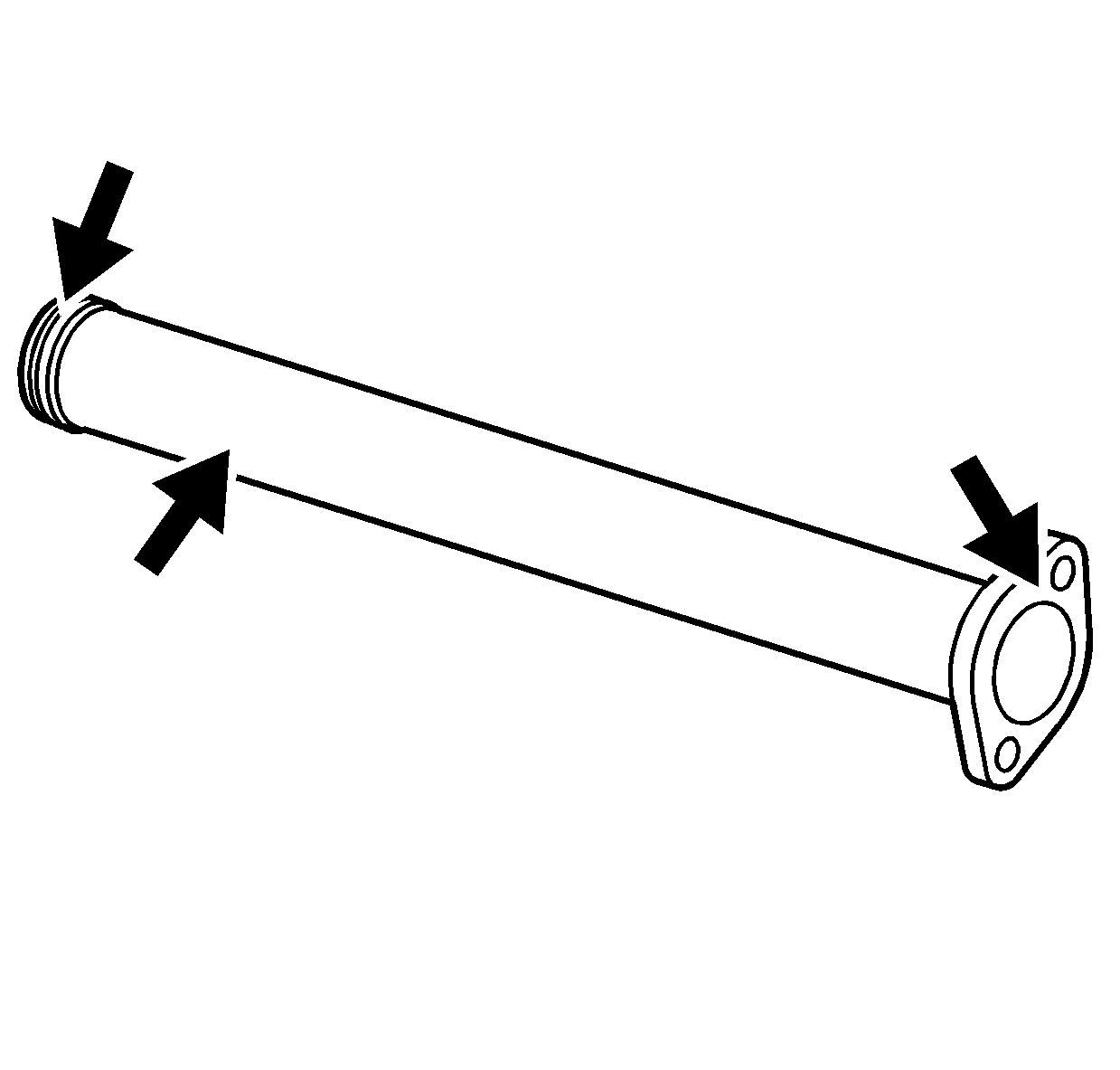
- Clean the water pump outlet pipe.
- Inspect the water pump outlet pipe for cracks.
- Inspect the water pump outlet pipe mating surfaces for damage.
- Clean the oil filter adapter.
- Inspect the oil filter adapter mating surfaces for damage.
- Replace any damaged components.
Installation Procedure
- Install new O-rings to the oil cooler assembly.
- Install a new O-ring onto the water pump outlet pipe.
- Lubricate the O-ring with engine coolant.
- Install the water pump outlet pipe to the oil filter adapter and oil cooler assembly.
- Install the gasket for the water pump outlet pipe on the water pump.
- Install the oil filter adapter and oil cooler assembly.
- Install the oil filter adapter and oil cooler assembly 5 bolts.
- Install a new seal in the coolant duct to the engine flywheel housing.
- Install a new gasket for the coolant duct to the oil filter adapter and oil cooler assembly.
- Install the 2 nuts for the coolant duct to engine flywheel housing.
- Install the 2 bolts for the coolant duct to oil filter adapter assembly.
- Install the engine wiring harness retainer on the water pump outlet pipe to water pump inner stud.
- Install the water pump outlet pipe nuts.
- Install the oil filter.
- Install the cross bar (4WD vehicle).
- Install the cross bar (RWD vehicle).
- Install the oil pan skid plate. (RWD shown).
- Install the left front fender wheelhouse inner panel (1).
- Install the left front tire. Refer to Tire and Wheel Removal and Installation in Tires and Wheels.
- Lower the vehicle.
- Fill the engine coolant. Refer to Cooling System Draining and Filling in Engine Cooling.
- Inspect the engine oil level and add as necessary.

Notice: Use the correct fastener in the correct location. Replacement fasteners must be the correct part number for that application. Fasteners requiring replacement or fasteners requiring the use of thread locking compound or sealant are identified in the service procedure. Do not use paints, lubricants, or corrosion inhibitors on fasteners or fastener joint surfaces unless specified. These coatings affect fastener torque and joint clamping force and may damage the fastener. Use the correct tightening sequence and specifications when installing fasteners in order to avoid damage to parts and systems.
Tighten
Tighten the oil filter adapter and oil cooler assembly bolts to 21 N·m
(15 lb ft).

Tighten
| • | Tighten the coolant duct bolts to 21 N·m (15 lb ft). |
| • | Tighten the coolant duct nuts to 21 N·m (15 lb ft). |

Tighten
Tighten the water pump outlet pipe nuts to 25 N·m (18 lb ft).

Tighten
Tighten the oil filter to contact plus 1 to 1-1/4 turn.

Tighten
Tighten the cross bar bolts to 100 N·m (74 lb ft).

Tighten
Tighten the cross bar bolts to 100 N·m (74 lb ft).

Tighten
Tighten the oil pan skid plate bolts to 20 N·m (15 lb ft).

