TIRE AND WHEEL RUNOUT MEASURING AND REPAIRING

VEHICLES AFFECTED: All Passenger Cars and Light Duty Trucks
This bulletin provides procedures for measuring and repairing excessive wheel and tire runout.
Some vehicles are very sensitive to tire and wheel assembly runout. Tires that are satisfactory on one vehicle might be unsatisfactory on another. When analyzing vibration problems, it is important to keep this in mind. In addition, different wheel positions on a vehicle may have differing sensitivity levels.
WHEN TO CHECK RUNOUT
You should check wheel runout or total wheel and tire runout in the following cases:
If the tire and wheel vibration occurs below 65 km per hour, there is good reason to suspect runout.
If all wheels are balanced well within one ounce of static balance and five ounces of dynamic balance, and a vibration occurs, you should check runout next.
If you see what appears to be a bulge in a tire or an out-of-round condition as a tire rotates on a balancer, you should check runout.
If you notice any wheel damage you should check runout.
If you discover a poor wheel fit on the hub and the vehicle exhibits vibration you should not rule out excessive runout.
Before condemning a tire for excessive runout, you should check wheel runout, unless the tire has an obvious problem.
RUNOUT MEASURING PROCEDURE
Runout measurements of the tire/wheel assembly can be taken both on and off the vehicle. These runouts also can be taken both radially and laterally. The measurements are taken with a dial indicator equipped with a roller contact point which:
1. Defines total runout in thousandths of an inch (roller contact point can be purchased from local tool suppliers).
2. Locates the high and low points of the runout.
The dial indicator is a delicate, precision instrument and should be handled accordingly. It should be used on a heavy, solid base to eliminate movement of the gauge when measuring runouts.
RADIAL RUNOUT
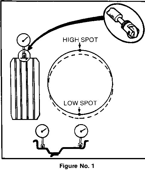
Radial runout is the egg-shaped deviation from a perfect circle (Reference Figure No. 1) and is measured perpendicularly on a circumference. On a tire/wheel assembly, this usually means measuring the centre thread rib (as shown on the left side of the diagram) although other tread ribs can be measured as well. The total runout is the reading from the gauge and the high spot (see diagram) is the location of the maximum runout. On a rim, if either flange is beyond guidelines, consider rim replacement.
LATERAL RUNOUT
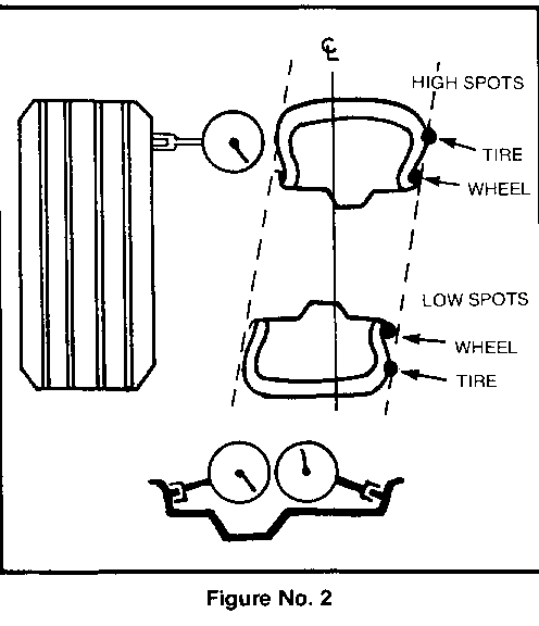
Lateral runout is a sideways variation causing a twist or wobble and is measured on a side surface (Reference Figure No. 2). On an assembly, measure the sidewall of the tire, as close to the tread shoulder design edge as possible. Again, the total runout is the reading from the gauge and the high spot is the location of the maximum runout. On a rim, if either flange is beyond guidelines, consider rim replacement.
RUNOUT GUIDELINES
Radial Runout Lateral Runout Thousandths Thousandths ----------- ------------
Mounted Tire - On Vehicle .060 in. .060 in.
Mounted Tire - Off Vehicle .050 in. .050 in.
Wheel Steel .040 in. .045 in. Aluminum .030 in. .030 in.
MEASUREMENT PROCEDURES
1. Inflate tires to specifications.
2. Warm up the tires prior to taking measurements to eliminate minute flat spotting, and this may be done during a ride test. Newly installed tires usually do not require warm up.
3. Raise the vehicle on a lift so that all four wheel & tire assemblies can be measured. If measurements are to be taken off the vehicle, mount each assembly on a dynamic balance machine.
4. Mark a stud bolt for future reference of original assembly position on hub. Also mark the assembly vehicle position on each tire.
5. Place the dial indicator in position to take either the radial or lateral measurement. Rotate the assembly (or wheel) to find the low spot. Adjust the gauge to read zero. Rotate the assembly once to ensure that the low spot has been located and that the dial returns to zero. Disregard any instantaneous dial jumps due to welds, paint runs, scratches, etc. on wheel.
6. Rotate the assembly slowly but constantly and note the amount of variance (runout) from zero on the dial of the gauge. Locate and mark the high spot.
If there is a large difference in runout measurements from ON vehicle to OFF vehicle, then the runout problem is probably due to excessive runout of the bolt circle or hub.
If measured runouts are not within the guidelines specified, proceed to vectoring to correct the problem.
VECTORING
Vectoring is a technique used to reduce radial or lateral runouts - and even dynamic balance on tire/wheel assemblies. Excessive runout is a source of ride complaints and vectoring can be used to minimize the runout. Vectoring can be accomplished by positioning of the tire on the wheel and positioning the assembly on the hub.
NOTE: Always rebalance assembly after vectoring. Tire to Wheel Vectoring
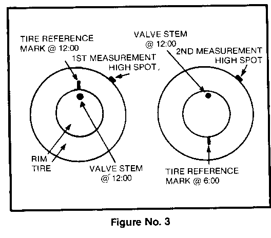
First determine the runout which needs to be minimized. This can often be done visually. If radial runout is the problem, take a measurement on the centre tread rib. If the tread is uneven, wrap tape tightly around the tire. (Assemblies can be measured most easily when mounted on a dynamic balance machine.) Record the runout magnitude and put a crayon mark at the high spot location (Reference Figure No. 3, left side).
If lateral runout is the problem, take a measurement on the sidewall just below the edge of the tread shoulder. Again, record the runout magnitude and put a crayon mark at the high spot location.
Take the assembly to the tire mounting machine. Put a reference crayon mark on the tire sidewall at the valve location. This is the 12 o'clock position. The location of the high spot is always with respect to the clock location on the wheel.
Break the assembly down and rotate the tire 6 hours (1800) on the rim (Reference Figure No. 3, right side). Reinflate the tire and measure the runout in question. Record the magnitude and the high spot location (valve stem is 12:00).
If the clock location of the high spot remained at or near the clock location of the original high spot, as is shown in the diagram, the rim is the major contributor to the runout problem. This can be confirmed by removing the tire from the wheel and checking the rim runout. If the rim runout exceeds guidelines it should be replaced.
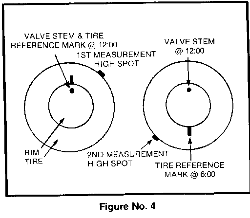
If the high spot is at or near a position 6 hours from the original high spot, as shown in Figure No. 4, the tire is the major contributor and should be replaced.
Following the tire to wheel vectoring, the assemblies should be rebalanced.
Assembly to Hub Vectoring
An on-vehicle runout check may indicate a problem source. One method to reduce this type of runout problem is by reindexing the assembly on the hub.
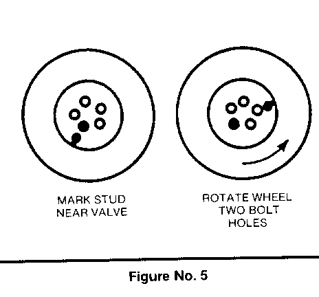
Mark the stud bolt nearest the valve stem (Reference Figure No. 5) for reference. Rotate the assembly two stud bolts (diagram below) and recheck the runout. Several positions may have to be tried to locate the optimum location. This can be effective for both radial and lateral runouts.
If there is some looseness in the wheel bolt holes, radial runout can be reduced by loosening the lug nuts slightly, moving the wheel position on the stud bolts and then re-rightening the lugs. The final stop to correct a wheel tire vibration is to on-vehicle balance the tire-wheel-brake assembly. This will supplement the off-vehicle dynamic balancing and compensate for imbalance in the brake rotor, drum or wheel cover.
General Motors bulletins are intended for use by professional technicians, not a "do-it-yourselfer". They are written to inform those technicians of conditions that may occur on some vehicles, or to provide information that could assist in the proper service of a vehicle. Properly trained technicians have the equipment, tools, safety instructions and know-how to do a job properly and safely. If a condition is described, do not assume that the bulletin applies to your vehicle, or that your vehicle will have that condition. See a General Motors dealer servicing your brand of General Motors vehicle for information on whether your vehicle may benefit from the information.
