DTC C0223 or C023 RF Wheel Speed Signal Erratic P32
| Table 1: | WSS Temperature vs. Sensor Resistance |
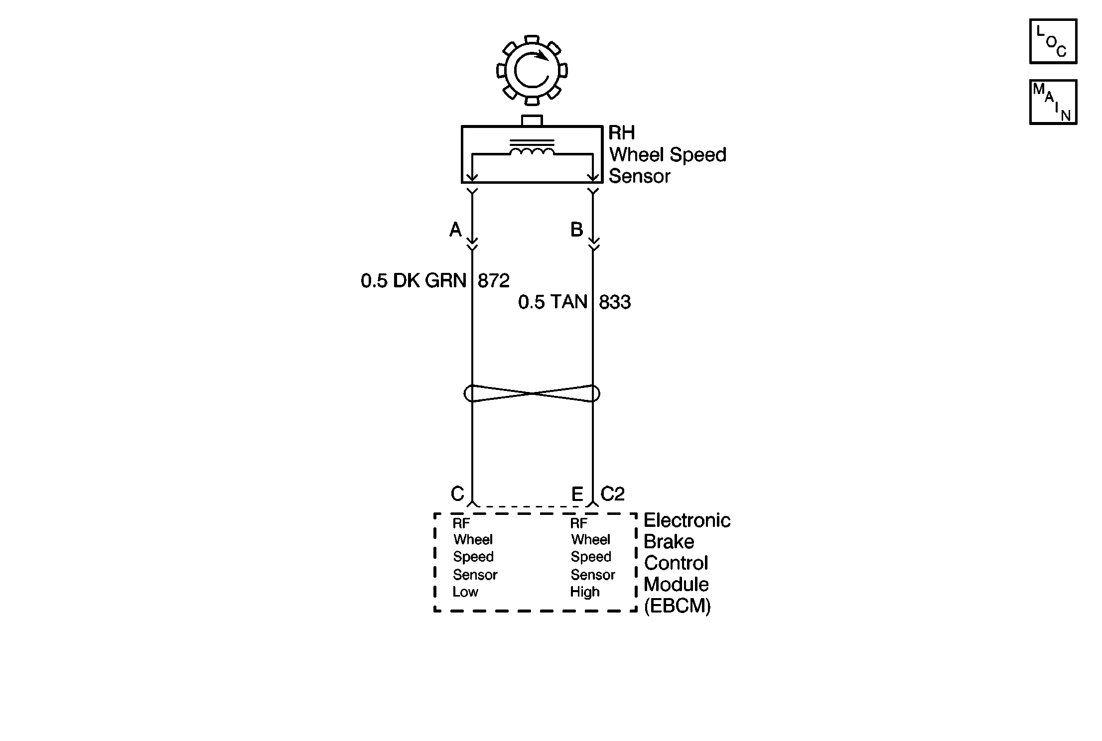
Circuit Description
The wheel speed sensor coil emits an electromagnetic field. A toothed ring on the wheel passes by the wheel speed sensor and disrupts this electromagnetic field. The disruption in the field causes the wheel speed sensor to produce a sinusoidal (AC) voltage signal. The frequency and amplitude of the sinusoidal (AC) voltage signal are proportional to the speed of the wheel. The amplitude of the wheel speed signal is also directly related to the distance between the wheel speed sensor coil and the toothed ring. This distance is referred to as the air gap.
Conditions for Setting the DTC
| • | The average wheel speed for all wheel signals is greater than 13 km/h (8 mph). |
| • | The right front wheel speed computation is greater than 33 km/h (20 mph) when the brake is applied or greater than 20 km/h (12 mph) when the brake is released. |
| • | No speed signal input to the EBCM from the right front wheel speed sensor for 15 milliseconds. Anything which sudenly prevents (intermittent) the right front wheel speed signal to drop to zero while the vehicle is moving greater than 40 km/h (25 mph). |
Action Taken When the DTC Sets
| • | The ABS indicator lamp turns on |
| • | The ABS disables |
DTC C0223 is an Ignition Latched DTC, which indicates that the above actions remain true until the ignition is turned to OFF (even if the cause of the DTC is intermittent).
Conditions for Clearing the DTC
| • | Repair the conditions responsible for setting the DTC |
| • | Use the Scan Tool Clear DTCs function |
Diagnostic Aids
Any of the following conditions may cause an intermittent malfunction:
| • | A poor connection |
| • | Wire insulation that is rubbed through |
| • | A wire breaks inside the insulation |
Thoroughly check any circuitry that is suspected of causing the intermittent complaint for the following conditions:
| • | Backed out terminals |
| • | Improper mating |
| • | Broken locks |
| • | Improperly formed or damaged terminals |
| • | Poor terminal to wiring connections |
| • | Physical damage to the wiring harness |
If the customer says that the ABS indicator lamp is on only during humid conditions such as rain, snow, or vehicle wash, then thoroughly inspect all wheel speed sensor circuits for signs of water intrusion. Use the following procedure:
- Spray the suspected area with a 5% salt water solution (two teaspoons of salt to 12 oz. of water)
- Drive the vehicle above 24 km/h (15 mph) for at least 30 seconds
If the DTC returns, replace the suspected harness.
When inspecting a wheel speed sensor, inspect the sensor terminals and the harness connector for corrosion. If evidence of corrosion exists, then replace the wheel speed sensor. Refer to Wheel Speed Sensor Replacement .
Resistance of the wheel speed sensor will increase with an increase in sensor temperature. Refer to the following tables for temperature/resistance values.
°C | °F | Ohms |
|---|---|---|
Temperature vs Resistance Values (Approximate) | ||
-40 to 4 | -40 to 40 | 1575 to 2420 |
5 to 43 | 41 to 110 | 1980 to 2800 |
44 to 93 | 111 to 200 | 2250 to 3280 |
94 to 150 | 201 to 302 | 2750 to 3850 |
Test Description
The numbers below refer to the steps in the diagnostic table:
-
This step checks the EBCM 4-way connector for looseness, corrosion, etc.
-
This step uses the wheel speed sensor resistance check to help isolate an intermittent connection.
-
This step checks the right front wheel speed sensor for the proper resistance.
-
This step checks for proper mounting and orientation of the right front wheel speed sensor.
Step | Action | Value(s) | Yes | No |
|---|---|---|---|---|
1 | Was the Diagnostic System Check performed? | -- | Go to Step 2 | |
2 |
Are all connections clean and tight? | -- | Go to Step 3 | Go to Step 6 |
Using a J 39200 , measure the resistance between terminal C and terminal E of the 4-way EBCM harness connector. Wiggle the WSS harness in various locations between the sensor and the EBCM while performing this measurement. Refer to the WSS temperature VS resistance table for the applicable resistance values. The values in this table are for sensor temperature not air temperature. Is the resistance measurement within the specified range without fluctuation when the harness is wiggled? | -- | Go to Step 5 | Go to Step 4 | |
Is the resistance measurement within the specified range? | -- | Go to Step 7 | Go to Step 8 | |
Is the wheel speed sensor and tone wheel in good condition? | -- | Go to Step 9 | Go to Step 10 | |
6 | Make necessary repairs to the 4-way EBCM harness connector. Refer to Connector Repairs . Is the repair complete? | -- | -- | |
7 | Repair the open, high resistance or short in CKT 833 or CKT 872. Refer to Wiring Repairs . Is the repair complete? | -- | -- | |
8 | Replace the right front wheel speed sensor. Refer to Wheel Speed Sensor Replacement . Is the repair complete? | -- | -- | |
9 | Malfunction is intermittent, perform the following:
Refer to Diagnostic aids for more information. Is the repair complete? | -- | -- | |
10 | Make necessary repairs. Is the repair complete? | -- | -- |
DTC C0223 or C023 RF Wheel Speed Signal Erratic P42
| Table 1: | WSS Temperature vs. Sensor Resistance |
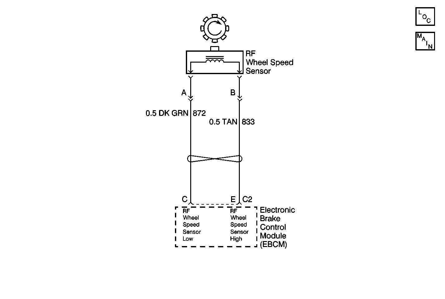
Circuit Description
The wheel speed sensor coil emits an electromagnetic field. A toothed ring on the wheel passes by the wheel speed sensor and disrupts this electromagnetic field. The disruption in the field causes the wheel speed sensor to produce a sinusoidal (AC) voltage signal. The frequency and amplitude of the sinusoidal (AC) voltage signal are proportional to the speed of the wheel. The amplitude of the wheel speed signal is also directly related to the distance between the wheel speed sensor coil and the toothed ring. This distance is referred to as the air gap.
Conditions for Setting the DTC
| • | The average wheel speed for all wheel signals is greater than 13 km/h (8 mph). |
| • | The right front wheel speed computation is greater than 33 km/h (20 mph) when the brake is applied or greater than 20 km/h (12 mph) when the brake is released. |
| • | No speed signal input to the EBCM from the right front wheel speed sensor for 15 milliseconds. Anything which sudenly prevents (intermittent) the right front wheel speed signal to drop to zero while the vehicle is moving greater than 40 km/h (25 mph). |
Action Taken When the DTC Sets
| • | The ABS indicator lamp turns on |
| • | The ABS disables |
DTC C0223 is an Ignition Latched DTC, which indicates that the above actions remain true until the ignition is turned to OFF (even if the cause of the DTC is intermittent).
Conditions for Clearing the DTC
| • | Repair the conditions responsible for setting the DTC |
| • | Use the Scan Tool Clear DTCs function |
Diagnostic Aids
Any of the following conditions may cause an intermittent malfunction:
| • | A poor connection |
| • | Wire insulation that is rubbed through |
| • | A wire breaks inside the insulation |
Thoroughly check any circuitry that is suspected of causing the intermittent complaint for the following conditions:
| • | Backed out terminals |
| • | Improper mating |
| • | Broken locks |
| • | Improperly formed or damaged terminals |
| • | Poor terminal to wiring connections |
| • | Physical damage to the wiring harness |
If the customer says that the ABS indicator lamp is on only during humid conditions such as rain, snow, or vehicle wash, then thoroughly inspect all wheel speed sensor circuits for signs of water intrusion. Use the following procedure:
- Spray the suspected area with a 5% salt water solution (two teaspoons of salt to 12 oz. of water)
- Drive the vehicle above 24 km/h (15 mph) for at least 30 seconds
If the DTC returns, replace the suspected harness.
When inspecting a wheel speed sensor, inspect the sensor terminals and the harness connector for corrosion. If evidence of corrosion exists, then replace the wheel speed sensor. Refer to Wheel Speed Sensor Replacement .
Resistance of the wheel speed sensor will increase with an increase in sensor temperature. Refer to the following tables for temperature/resistance values.
°C | °F | Ohms |
|---|---|---|
Temperature vs Resistance Values (Approximate) | ||
-40 to 4 | -40 to 40 | 1575 to 2420 |
5 to 43 | 41 to 110 | 1980 to 2800 |
44 to 93 | 111 to 200 | 2250 to 3280 |
94 to 150 | 201 to 302 | 2750 to 3850 |
Test Description
The numbers below refer to the steps in the diagnostic table:
-
This step checks the EBCM 4-way connector for looseness, corrosion, etc.
-
This step uses the wheel speed sensor resistance check to help isolate an intermittent connection.
-
This step checks the right front wheel speed sensor for the proper resistance.
-
This step checks for proper mounting and orientation of the right front wheel speed sensor.
Step | Action | Value(s) | Yes | No |
|---|---|---|---|---|
1 | Was the Diagnostic System Check performed? | -- | Go to Step 2 | |
2 |
Are all connections clean and tight? | -- | Go to Step 3 | Go to Step 6 |
Using a J 39200 , measure the resistance between terminal C and terminal E of the 4-way EBCM harness connector. Wiggle the WSS harness in various locations between the sensor and the EBCM while performing this measurement. Refer to the WSS temperature Vs resistance table for the applicable resistance values. The values in this table are for the sensor temperature not air temperature. Is the resistance measurement within the specified range without fluctuation when the harness is wiggled? | -- | Go to Step 5 | Go to Step 4 | |
Is the resistance measurement within the specified range? | -- | Go to Step 7 | Go to Step 8 | |
Is the wheel speed sensor and tone wheel in good condition? | -- | Go to Step 9 | Go to Step 10 | |
6 | Make necessary repairs to the 4-way EBCM harness connector. Refer to Connector Repairs . Is the repair complete? | -- | -- | |
7 | Repair the open, high resistance or short in CKTs 833 or 872. Refer to Wiring Repairs . Is the repair complete? | -- | -- | |
8 | Replace the right front wheel speed sensor. Refer to Wheel Speed Sensor Replacement . Is the repair complete? | -- | -- | |
9 | Malfunction is intermittent, perform the following:
Refer to Diagnostic aids for more information. Is the repair complete? | -- | -- | |
10 | Make necessary repairs. Is the repair complete? | -- | -- |
