Circuit Description
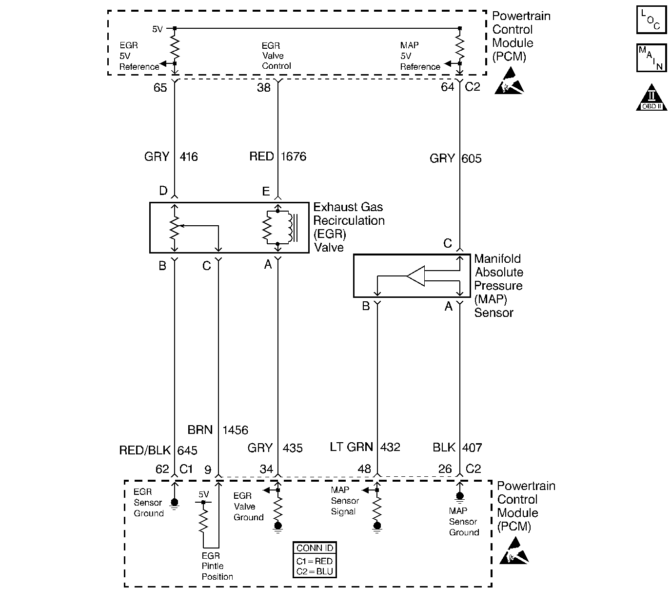
The Manifold Absolute Pressure (MAP) sensor is mounted in front of the intake manifold. The MAP sensor measures pressure changes within the intake manifold, which is an indication of engine load. The MAP sensor has a 5.0 volt reference, a ground and a signal circuit. The MAP sensor contains diaphragm which changes resistance based on pressure. When manifold pressure is low (high vacuum) sensor output voltage is low. When manifold pressure is high (low vacuum) sensor output voltage is high. MAP sensor voltage (depending on altitude) can range from 1.0-1.5 volts at idle (high vacuum) to 4.0-4.9 volts at wide open throttle (low vacuum). When the PCM senses a signal voltage lower than the normal operating range of the sensor, this DTC will set.
Conditions for Setting the DTC
The following conditions will set the DTC:
| • | No TP sensor faults are set. |
| • | The engine is operating. |
| • | The TP is at least 0% when engine speed is no more than 800 RPM. |
| • | Or the TP is at least 12.5% when the engine speed is greater than 800 RPM. |
Action Taken When the DTC Sets
| • | The PCM stores the DTC information into memory when the diagnostic runs and fails. |
| • | The malfunction indicator lamp (MIL) will not illuminate. |
| • | The PCM records the operating conditions at the time the diagnostic fails. The PCM stores this information in the Failure Records. |
Conditions for Clearing the MIL/DTC
| • | A History DTC will clear after 40 consecutive warm-up cycles, if no failures are reported by this or any other non-emission related diagnostic. |
| • | A last test failed (Current DTC) will clear when the diagnostic runs and does not fail. |
| • | The PCM battery voltage is interrupted. |
| • | Use a scan tool in order to clear the MIL/DTC. |
Diagnostic Aids
| • | An intermittent open in the MAP sensor signal circuit or the 5 volt reference circuit will result in a DTC P1107. |
| • | With the ignition ON and the engine OFF, the manifold pressure is equal to atmospheric pressure with the signal voltage high. The PCM uses this information as an indication of the vehicle's altitude. Comparison of this reading with a known good vehicle using the same sensor is a good way to check accuracy of a suspect sensor. Readings should be the same ±0.4 volts. |
| • | An intermittent open in the MAP sensor signal circuit or the 5 volt reference circuit will result in a DTC P1107. |
| • | The PCM 5.0 volt reference circuits are internally connected within the PCM. If all the MAP sensor circuits check to be OK, inspect all PCM 5.0 volt reference component/circuits for a malfunction. |
Refer to Symptoms .
Important: The electrical connector must remain securely fastened.
Important: After removing the MAP sensor from the intake manifold, replace the MAP Sensor to intake manifold seal.
Remove the MAP sensor. Twist the sensor by hand (only) in order to check for intermittent connections. Output changes greater than 0.1 volt indicates a bad connector or connection. If OK, replace sensor.Test Description
The numbers below refer to the step numbers on the diagnostic table.
-
If DTC P0107 failed this ignition, this indicates a hard failure is present. When a hard failure is present, both the hard and intermittent DTCs set.
-
Using the Freeze Frame and/or Failure Records data may aid in locating an intermittent condition. If you cannot duplicate the DTC, the information included in the Freeze Frame and/or Failure Records data can help determine how many miles since the DTC set. The Fail Counter and Pass Counter can also help determine how many ignition cycles the diagnostic reported a pass and/or a fail. Operate the vehicle within the same freeze frame conditions (RPM, load, vehicle speed, temperature etc.) that you observed. This will isolate when the DTC failed.
-
If the scan tool displays 5.0 volts, the MAP sensor signal, 5.0 volt reference circuit, and the PCM are OK. For any test that requires probing the PCM or component harness connectors, use the Connector Test Adapter Kit J 35616 . Using this kit will prevent any damage to the harness connector terminals.
-
If the scan tool displays 5.0 volts, the MAP sensor signal circuit and the PCM are OK. For any test that requires probing the PCM or component harness connectors, use the Connector Test Adapter Kit J 35616 . Using this kit will prevent any damage to the harness connector terminals.
-
Disconnecting the PCM allows using the DMM J 39200 in order to check the continuity of the circuits. This aids in locating an open or a shorted circuit.
Step | Action | Value(s) | Yes | No | ||||||
|---|---|---|---|---|---|---|---|---|---|---|
1 | Did you perform the Powertrain On-Board Diagnostic (OBD) System Check? | -- | ||||||||
Monitor the MAP sensor voltage on Engine 1 Data List on the scan tool. Is the MAP sensor voltage below the specified value? | 0.10V | |||||||||
Does the scan tool indicate that this diagnostic failed this ignition? | -- | Go to Diagnostic Aids | ||||||||
Is the MAP sensor voltage near the specified value? | 5.0V | |||||||||
Is the MAP sensor voltage near the specified value? | 5.0V | |||||||||
Did you find the 5.0 volt reference circuit open or shorted to a ground? | -- | |||||||||
7 |
Did the terminal require replacement? | -- | ||||||||
8 |
Did you find the MAP sensor signal circuit open or shorted to a ground? | -- | ||||||||
9 | Check the MAP sensor signal circuit for a poor connection at the PCM and replace the terminal if necessary. Refer to Body and Accessories/Wiring Systems. Did the terminal require replacement? | -- | ||||||||
10 | Replace the MAP sensor. Refer to Manifold Absolute Pressure Sensor Replacement . Is the action complete? | -- | -- | |||||||
11 |
Important:: Program the replacement PCM. Refer to Powertrain Control Module Replacement . Replace the PCM. Is the action complete? | -- | -- | |||||||
12 |
Does the scan tool indicate that this test ran and passed? | -- | ||||||||
13 | Select the Capture Info option and the Review Info option using the scan tool. Does the scan tool display any DTCs that you have not diagnosed? | -- | Go to the applicable DTC table | System OK |
