GM Service Manual Online
For 1990-2009 cars only
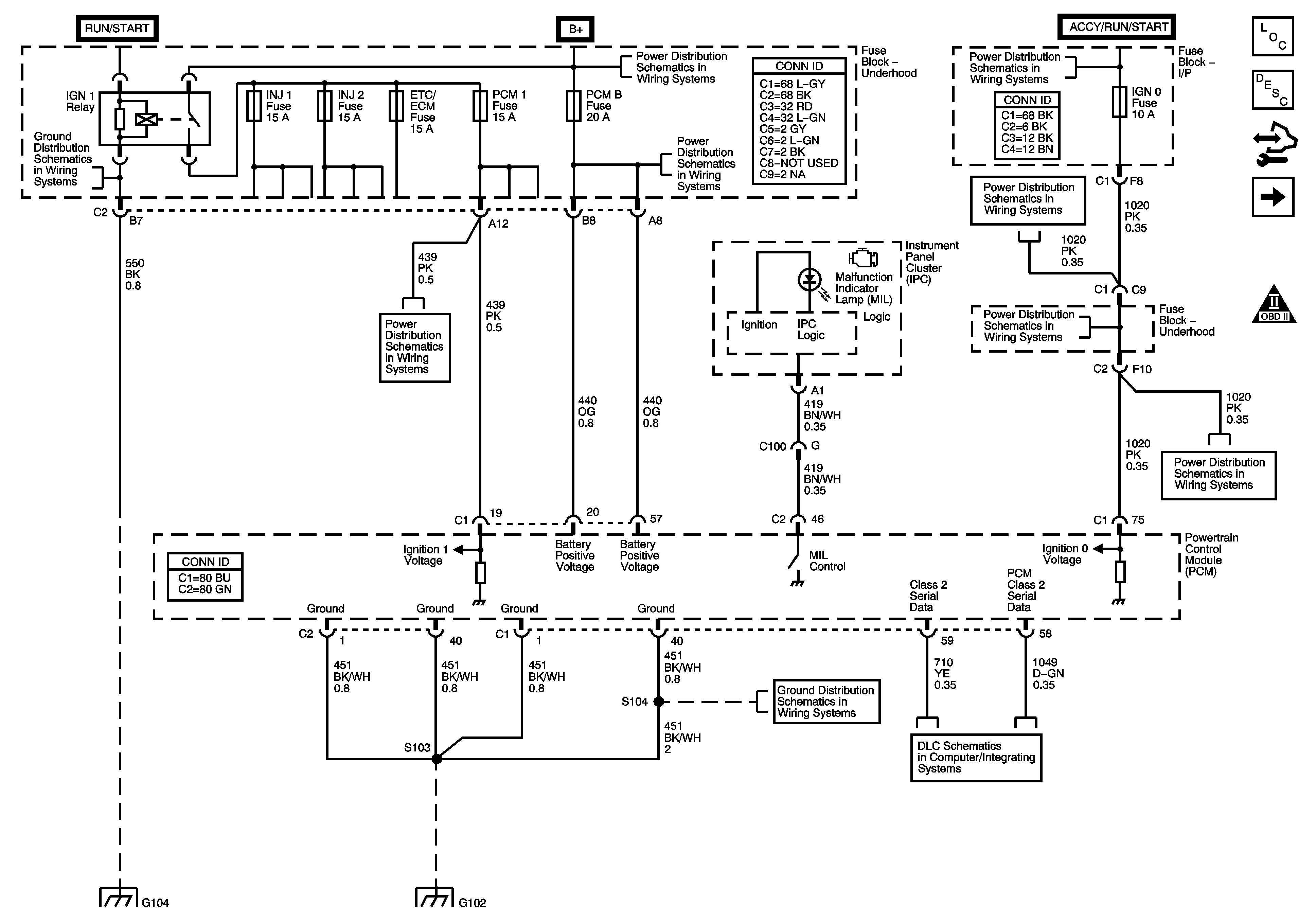
Figure 1:

Module Power, Ground, Serial Data and MIL

Object Number: 1467924  Size: FS
Master Electrical Component List
Powertrain Control Module Description
5 Volt and Low Reference Busses
OBD II Symbol Description Notice
G104 and G106
ETC/ECM, PCM I, INJ 1, and INJ 2 Fuses
B+Bus
PCM B, TREC, IPC/DIC, TBC BATT, SEO B1, SEO B2, and HVAC/ECAS Fuses
WS WPR, SEO ACCY, RR WPR, TBC ACCY, TBC IGN 0, and IGN 0 Fuses
Power, Ground, DLC, and Splice Pack SP205
G102 and G103
G102 and G103
G104 and G106
Figure 2:

Engine Data Sensors - 5-Volt and Low Reference
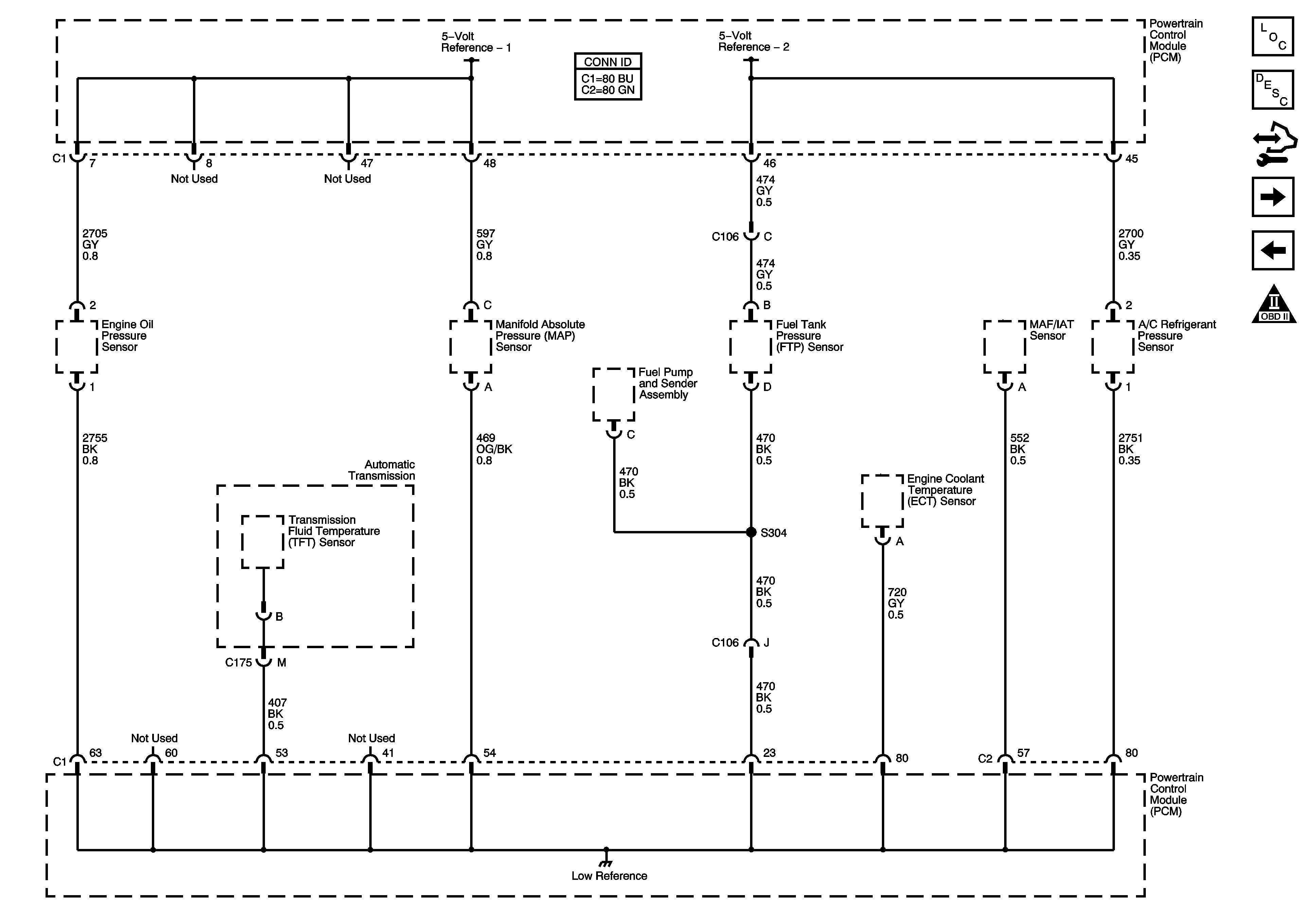

Object Number: 1467930  Size: FS
Master Electrical Component List
Powertrain Control Module Description
MAP, ECT, VSS Circuit, and IAT/MAF
PCM Power, Grounding, Serial Data, and MIL
OBD II Symbol Description Notice
Figure 3:

Engine Data Sensors - Pressure, Temperature, MAF and VSS
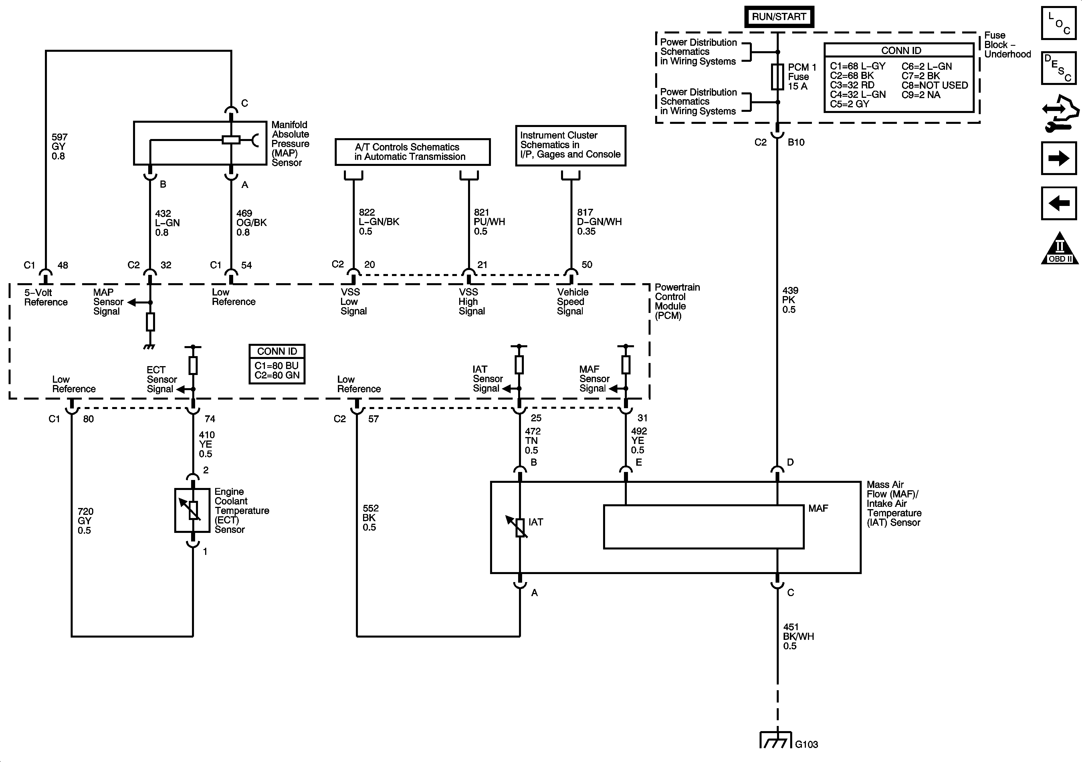

Object Number: 1467931  Size: FS
Master Electrical Component List
Powertrain Control Module Description
HO2S Circuits
5 Volt and Low Reference Busses
OBD II Symbol Description Notice
ETC/ECM, PCM I, INJ 1, and INJ 2 Fuses
Fluid Pressure Switch, TFT Sensor, PC Solenoid Valve, Transfer Case Control Module, and Vehicle Speed Sensor
G102 and G103
Power, Grounding, DLC, Sensors, and Gauges
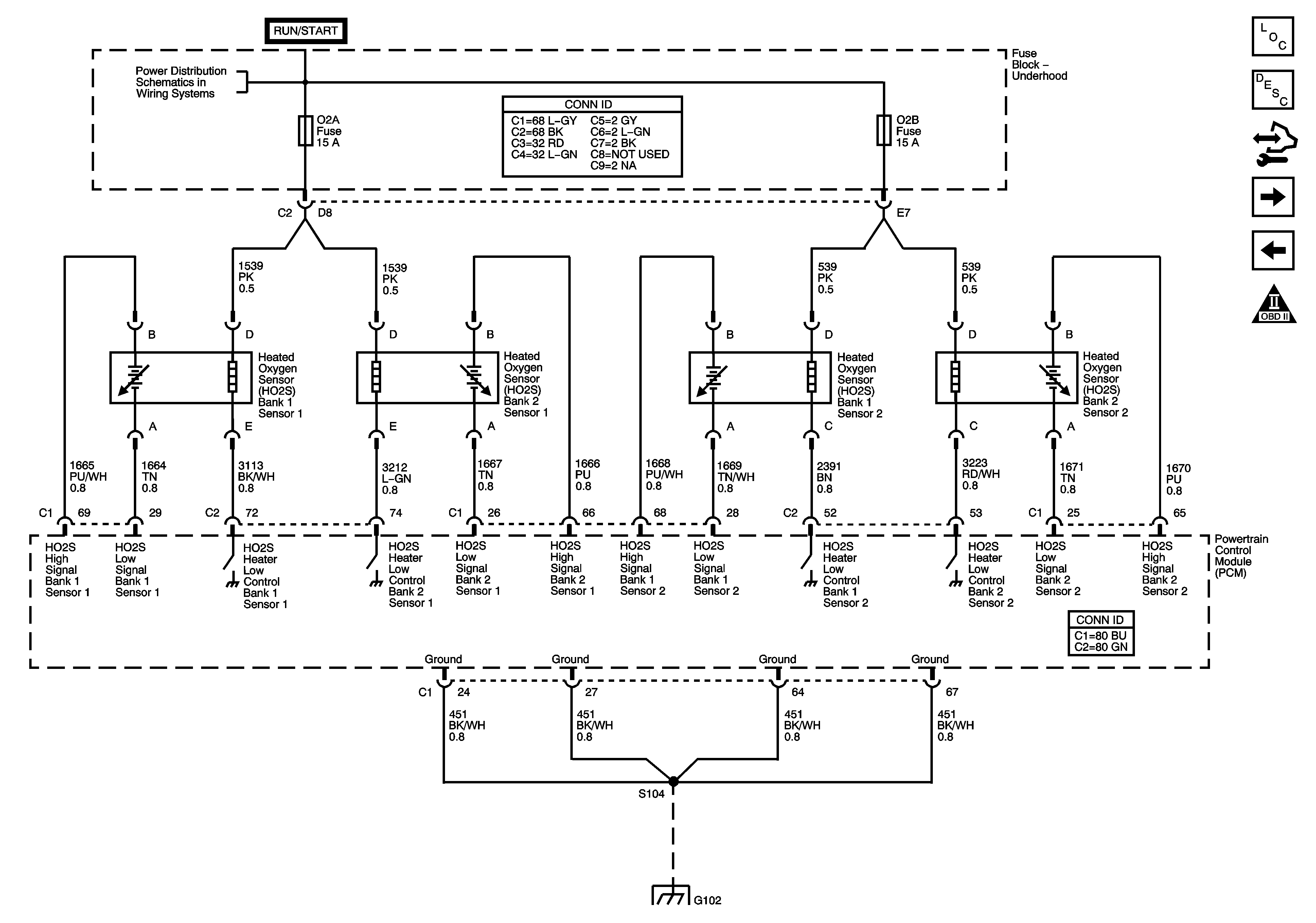
Figure 4:

Engine Data Sensors - Oxygen Sensors


Object Number: 1467933  Size: FS
Master Electrical Component List
Powertrain Control Module Description
TAC Power, Grounding, Data Circuits, and Indicator Control
MAP, ECT, VSS Circuit, and IAT/MAF
OBD II Symbol Description Notice
B/U LP, O2A, O2B, TBC IGN 1, TRL B/U, and BTSI Fuses
G102 and G103
Figure 5:

Engine Data Sensors - Throttle Actuator Controls
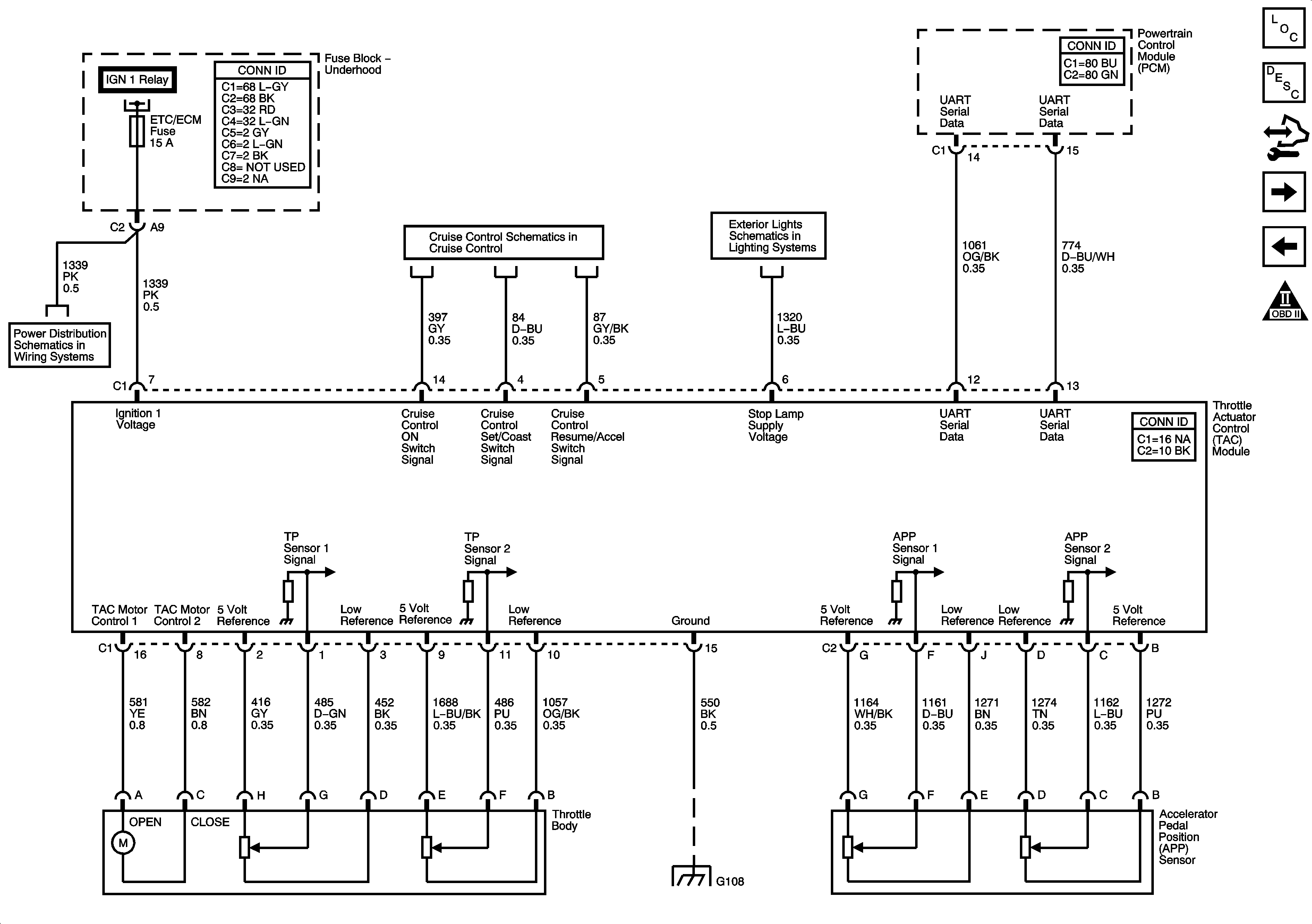

Object Number: 1467937  Size: FS
Master Electrical Component List
Throttle Actuator Control (TAC) System Description
Accelerator Pedal Position Sensor and Throttle Control Circuits
HO2S Circuits
OBD II Symbol Description Notice
ETC/ECM, PCM I, INJ 1, and INJ 2 Fuses
Stop Lamps
Power, Ground, DLC, and Splice Pack SP205
G104 and G106
Figure 6:

Ignition Controls - Ignition System Coils 1, 3, 5 and 7
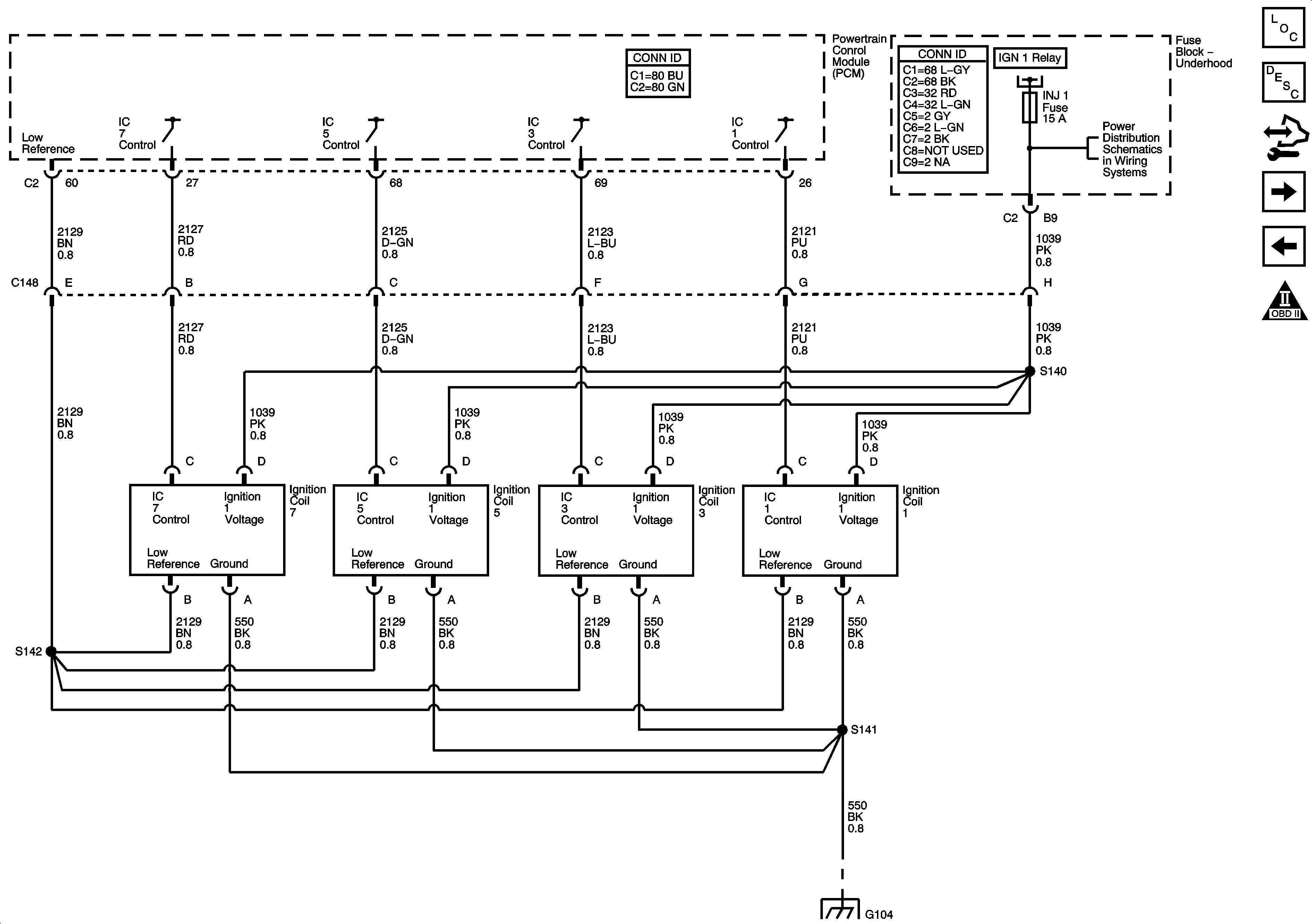

Object Number: 1467940  Size: FS
Master Electrical Component List
Electronic Ignition (EI) System Description
Ignition Control, Bank 2
Accelerator Pedal Position Sensor and Throttle Control Circuits
OBD II Symbol Description Notice
ETC/ECM, PCM I, INJ 1, and INJ 2 Fuses
G104 and G106
Figure 7:

Ignition Controls - Ignition System Coils 2, 4, 6 and 8
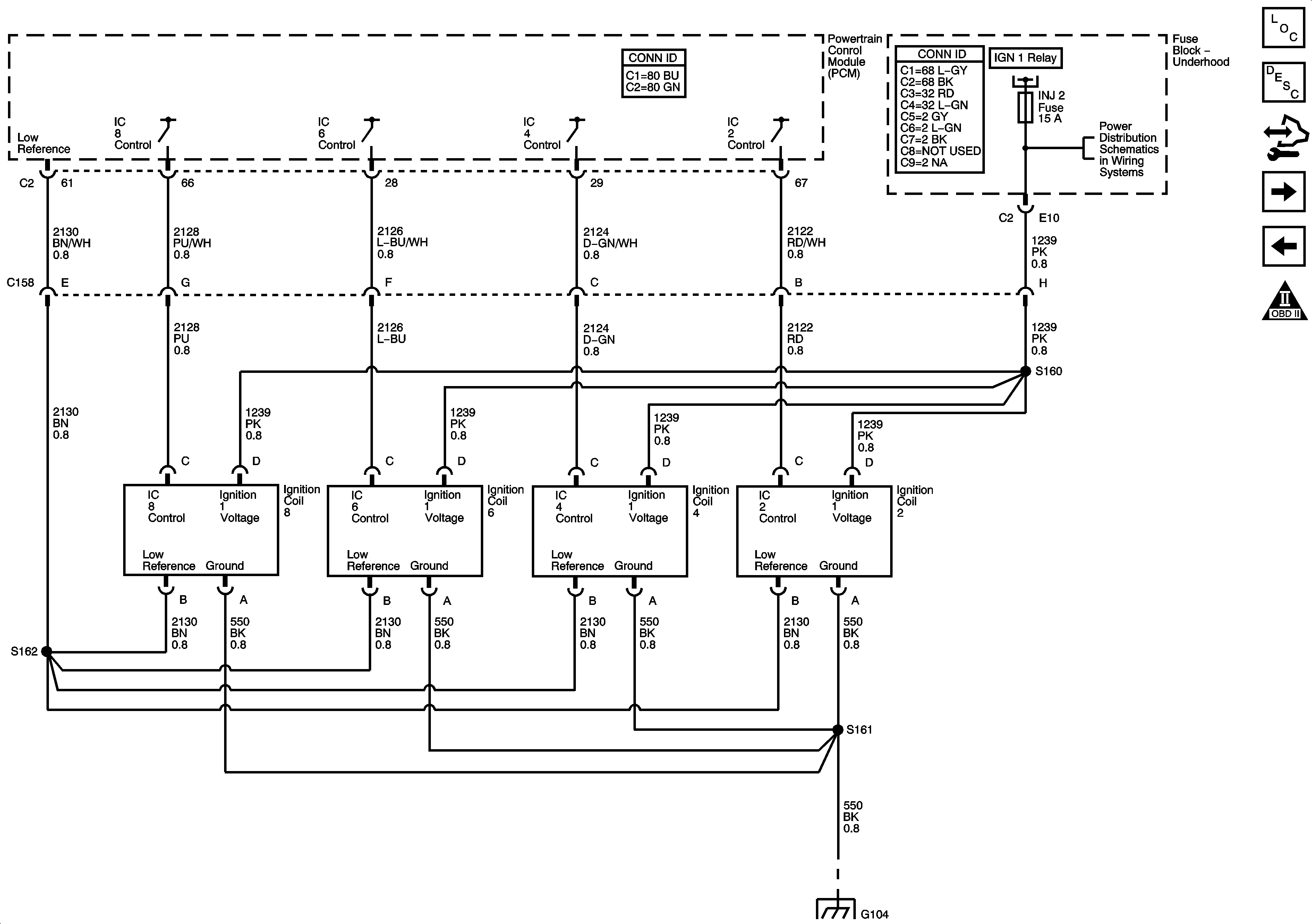

Object Number: 1467942  Size: FS
Master Electrical Component List
Electronic Ignition (EI) System Description
CMP, CKP, KS, and Engine Speed Output
Ignition Control, Bank 1
OBD II Symbol Description Notice
ETC/ECM, PCM I, INJ 1, and INJ 2 Fuses
G104 and G106
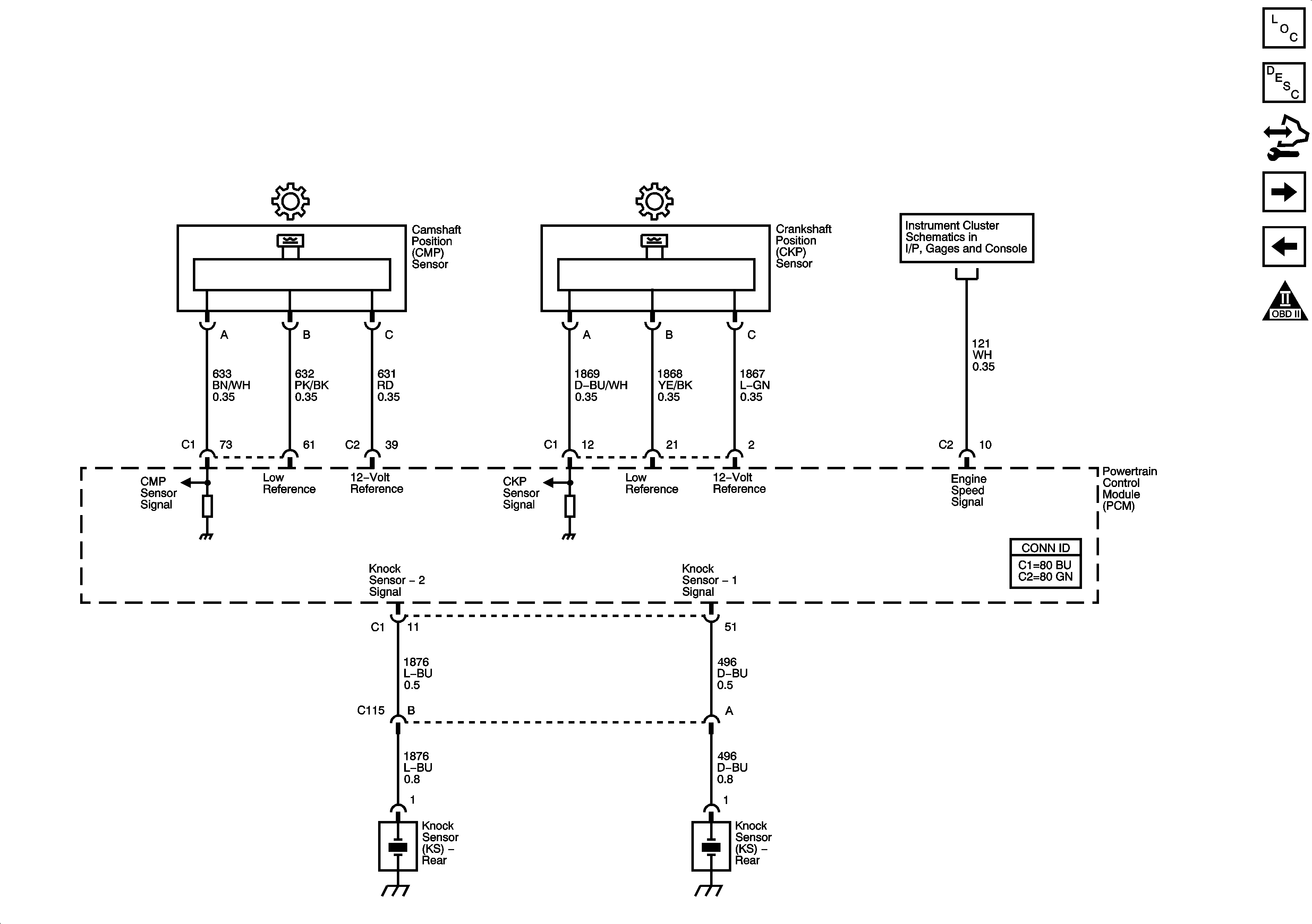
Figure 8:

Ignition Controls - Sensors


Object Number: 1467945  Size: FS
Master Electrical Component List
Knock Sensor (KS) System Description
Fuel Pump Controls
Ignition Control, Bank 2
OBD II Symbol Description Notice
Figure 9:

Fuel Controls - Fuel Pump Controls and Fuel Injectors
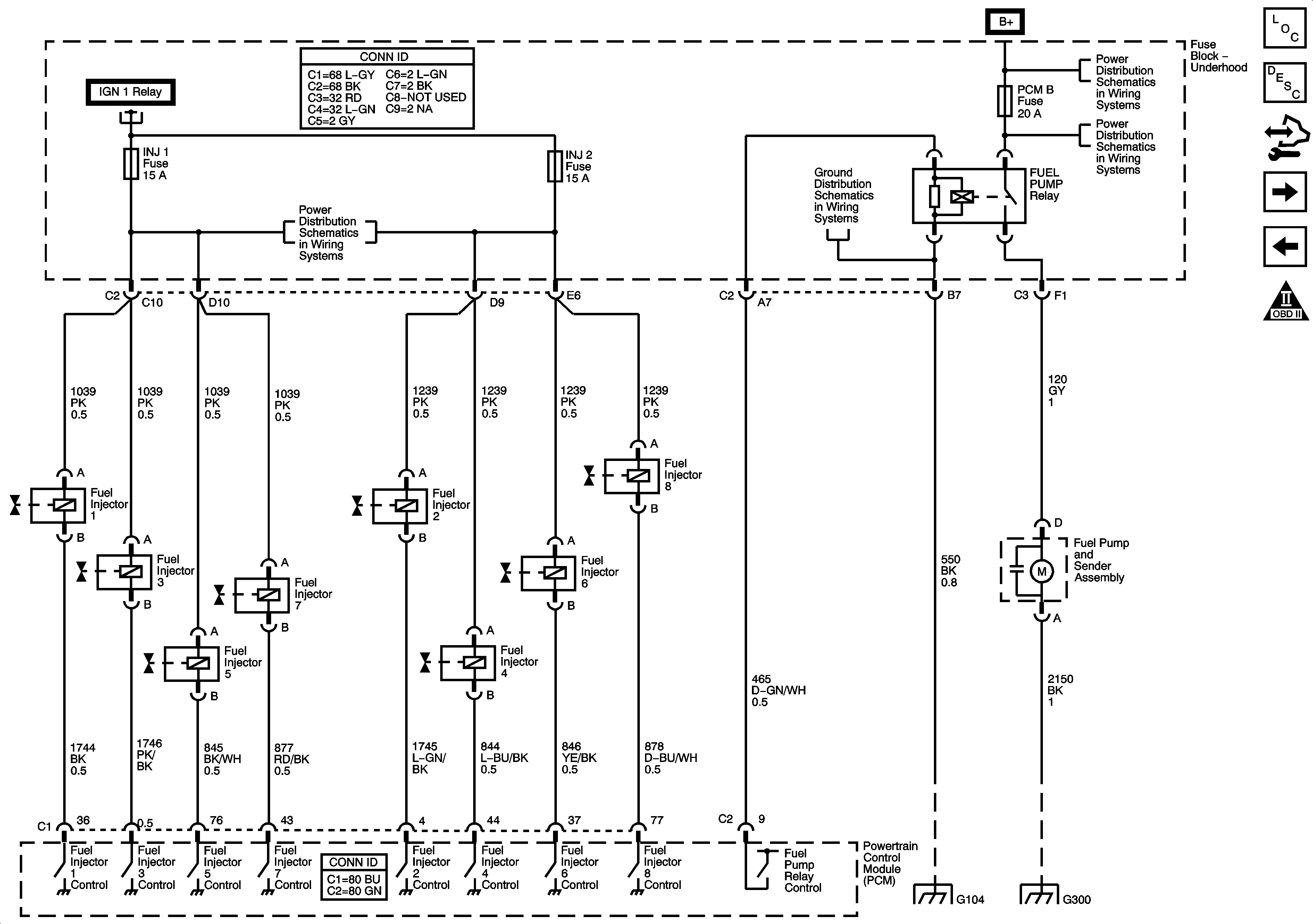

Object Number: 1467948  Size: FS
Master Electrical Component List
Fuel System Description Without Returnless Fuel System
Fuel Injector Controls
CMP, CKP, KS, and Engine Speed Output
OBD II Symbol Description Notice
PCM B, TREC, IPC/DIC, TBC BATT, SEO B1, SEO B2, and HVAC/ECAS Fuses
G104 and G106
G308, G310, G401, and G300
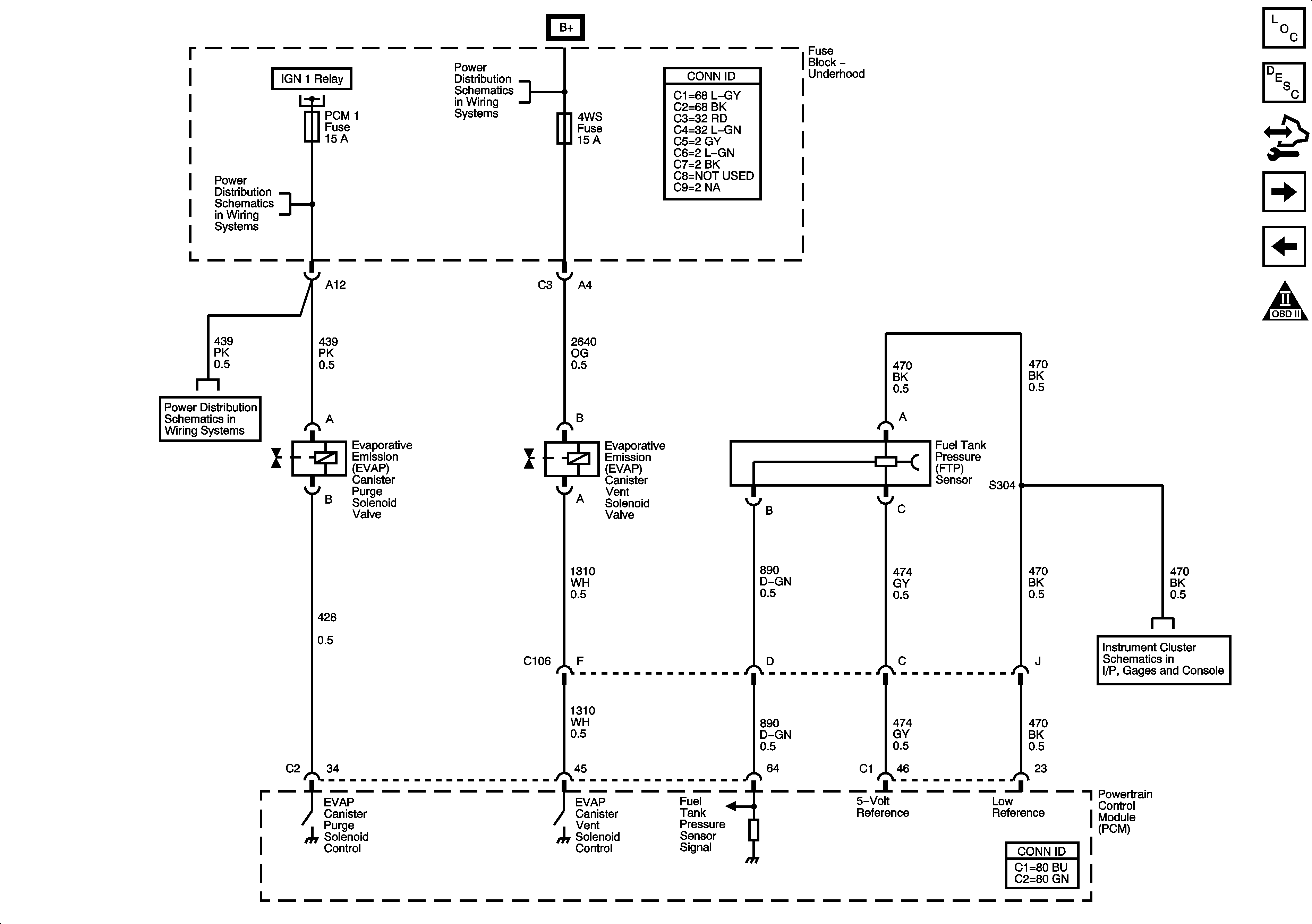
Figure 10:

Fuel Controls - EVAP Controls


Object Number: 1467949  Size: FS
Master Electrical Component List
Evaporative Emission Control System Description
HVAC and Cruise Control Circuits
Fuel Injector Controls
OBD II Symbol Description Notice
G104 and G106
ETC/ECM, PCM I, INJ 1, and INJ 2 Fuses
RR DEFOG, RR WPR, 4WS, STOP LP, VEH STOP, and VEH CHMSL Fuses
Power, Grounding, DLC, Sensors, and Gauges
G104 and G106
Figure 11:

Transmission and Controlled/Monitored Subsystem References
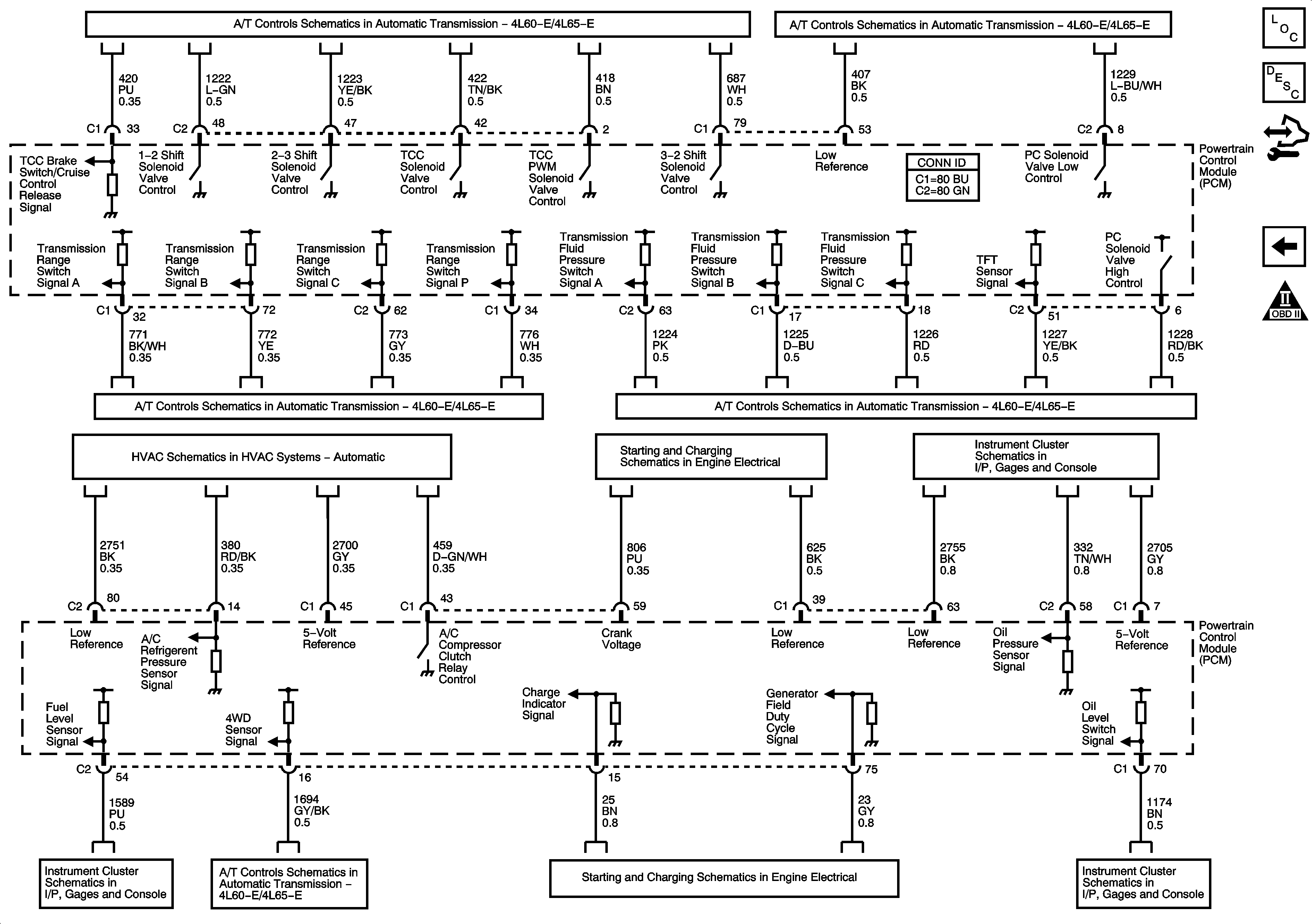

Object Number: 1467951  Size: FS
Master Electrical Component List
Powertrain Control Module Description
Starter, Generator, Oil Level and Pressure, and 4WD Circuits
OBD II Symbol Description Notice
Power, BCM, PCM, Class 2, Stop Lamp Switch, Tow/Haul Switch, and Shift Solenoids
Fluid Pressure Switch, TFT Sensor, PC Solenoid Valve, Transfer Case Control Module, and Vehicle Speed Sensor