THROTTLE BODY DRIVE UNIT (DIAG RPL. THROTTLE DRIVE COVER ASSY

SUBJECT: THROTTLE BODY DRIVE UNIT
MODELS: 1990-91 School Bus Chassis Equipped With 6.OL Gas Engines (LSO)
TO: ALL GENERAL MOTORS DEALERS
General Motors of Canada Limited has determined that a defect, which relates to motor vehicle safety, exists in certain 1990-91 B6 School Bus chassis equipped with 6.OL engines (LSO). A manufacturing condition in the TBI unit may have occurred that could allow the throttle cam lever to disengage from the throttle drive shaft. When this occurs, the engine could go to wide open throttle. If RPM reaches 4,000, the governor is actuated, preventing the engine from exceeding 4,000 RPM. Although the vehicle can still be stopped with the service brake, loss of accelerator control could result in a vehicle crash without prior warning.
To ensure this condition does not exist, the dealer will inspect for proper throttle cam lever to shaft attachment and, if necessary, replace the throttle drive cover assembly. IT IS ANTICIPATED THAT VERY FEW DRIVE THROTTLE COVER ASSEMBLIES WILL NEED TO BE REPLACED.
VEHICLES INVOLVED:
Involved are certain 1990-91 B6 School Bus chassis equipped with 6.OL engines (LSO).
Model Year Model From Through ----- ----- ---- ------- 1990 B6 SOP EOP 1991 B6 SOP EOP
All affected vehicles have been identified by the VIN listing provided to involved dealers with this bulletin. Any dealer not receiving a listing was not shipped any of the affected vehicles.
DEALER CAMPAIGN RESPONSIBILITY:
All unsold new vehicles in dealer's possession and subject to this campaign be held and inspected/repaired per the Service Procedure of this campaign Bulletin before owners take possession of these vehicles.
Dealers are to perform this campaign on all involved vehicles at no charge to owners, regardless of kilometres traveled, age of vehicle, or ownership, from this time forward.
Owners of vehicles recently sold from your new vehicle inventory with no owner information indicated on the dealer listing, are to be contacted by the dealer, and arrangements made to make the required correction according to instructions contained in this bulletin. This could be done by mailing to such owners a copy of die owner letter accompanying this bulletin. Campaign follow- up cards should not be used for this purpose, since the owner may not as yet have received the notification letter.
In summary, whenever a vehicle subject to this campaign is taken into your new or used vehicle inventory, or is in your dealership for service in the future, please take the steps necessary to be sure the campaign correction has been made before selling or releasing the vehicle.
CAMPAIGN PROCEDURE:
Refer to Section 4 of the Service Policies and Procedures Manual for the detailed procedure on handling Product Campaigns. Dealers are requested to complete the campaign on all transfers as soon as possible.
OWNER NOTIFICATION:
All owners of record at the time of campaign release are shown on the attached computer listing and have been notified by first class mail from General Motors (see copy of owner letter included with this bulletin). The listings provided are for campaign activity only and should not be used for any other purpose.
PARTS INFORMATION:
IT IS ANTICIPATED THAT VERY FEW THROTTLE DRIVE COVER ASSEMBLIES WILL NEED TO BE REPLACED. HOWEVER, IF THROTTLE DRIVE COVER IS REQUIRED IT MUST BE OBTAINED FROM GENERAL MOTORS AC - ROCHESTER (716-647-7240). DO NOT ORDER THROTTLE DRIVE COVER FROM GM SERVICE PARTS OPERATION (GMSPO).
Part Number Description Quantity/Vehicle ----------- ----------- ---------------- NPN Throttle Drive Cover Assembly 1 12345382 Thread Locking Compound As Required
PARTS AND LABOUR CLAIM INFORMATION:
Credit for the campaign work performed will be paid upon receipt of a properly completed campaign claim card or DCS transmission in accordance with the following:
Repair Code Description Time Allowance ----------- ----------- -------------- 2A Inspect and/or Replace .5 Throttle Drive Cover Assembly
Time allowance includes 0.1 hour for dealer administrative detail associated with this campaign. Parts credit will be based on dealer net plus 30% to cover parts handling.
SERVICE PROCEDURE:
1. Disconnect negative battery cable.
2. Remove left inner fender panel (if equipped).
3. Remove air cleaner assembly, extension (spacer), and gasket.
4. Remove governor drive motor connector locking tab insert and disconnect wiring harness connector from drive motor.
5. Disconnect throttle cable from throttle lever cam.
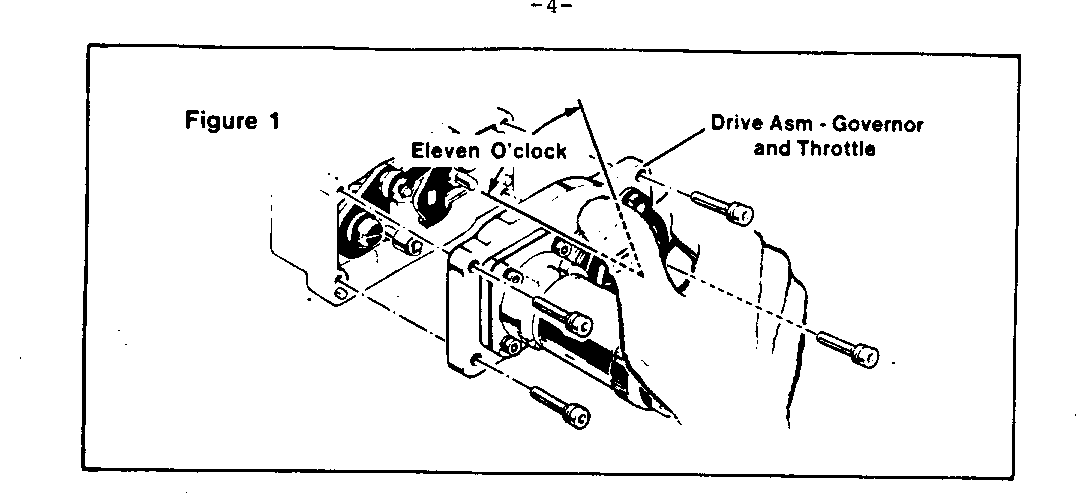
6. Remove the four (4) governor and throttle drive assembly cover plate screws. (See Figure 1)
NOTICE: Throttle lever cam spring is under tension. Hold throttle valves (plates) closed, then rotate throttle lever cam clockwise until the cable barrel connection hole reaches 11 o'clock position. This procedure will prevent sudden release of spring tension as throttle drive assembly is removed from throttle body.
7. Remove governor and throttle drive assembly cover plate.
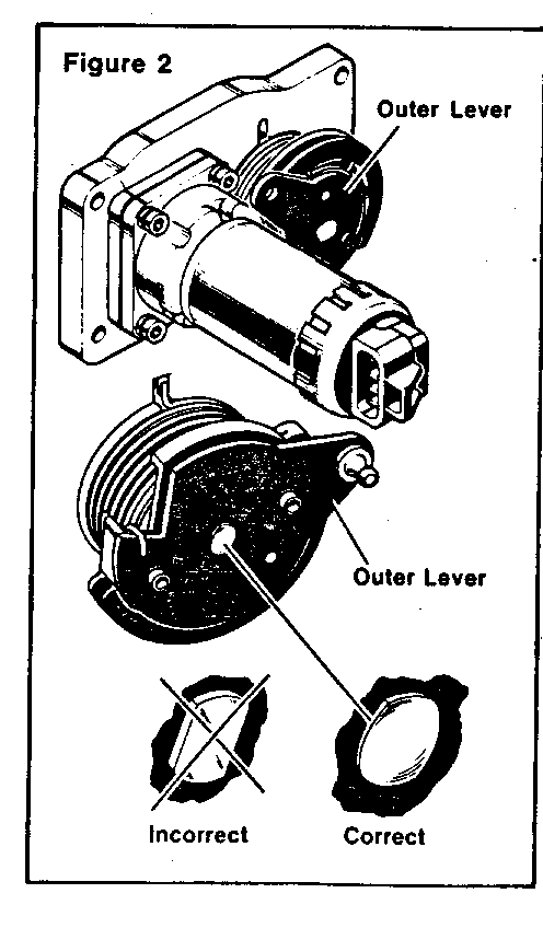
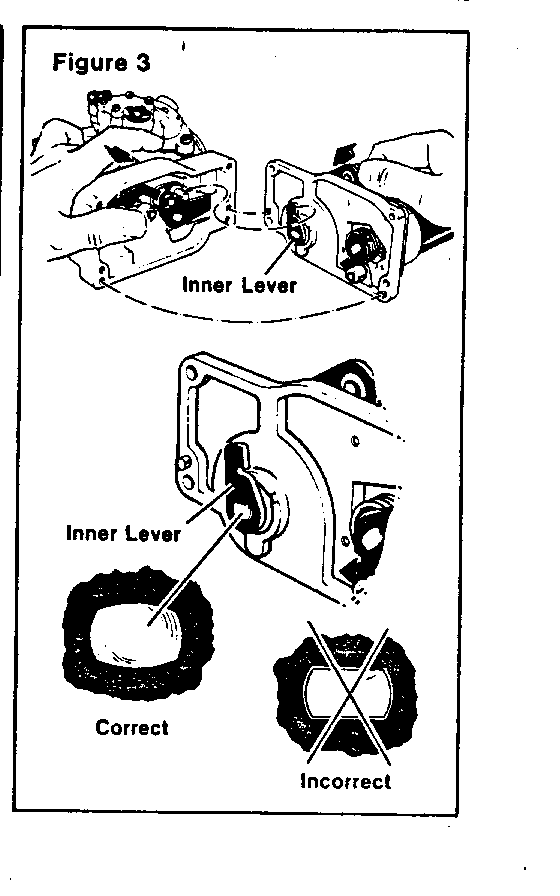
8. Inspect throttle lever shaft at both ends for proper attachment of inner and outer levers to shaft (See Figures 2 & 3) A properly attached inner and outer lever will have shaft material riveted or peened over, securing both levers.
9. If throttle levers are properly affixed to the lever shaft, reinstall throttle drive assembly. If throttle levers are not properly affixed to shaft, contact AC-Rochester (716-647-7240) for replacement part. DO NOT RELEASE VEHICLE TO OWNER UNTIL REPAIRS ARE COMPLETED.
Install throttle drive assembly by first holding throttle valves closed, then rotate the throttle lever cam clockwise until the cable barrel connection hole is in the 11 o'clock position. (See Figure 1) This will align the throttle cam with the throttle drive linkage.
10. Holding the cam in place, position throttle drive assembly cover plate on the throttle body. Release cam and hold cover plate in place.
11. Install the four (4) governor and throttle drive cover attaching screws coated with thread locking compound (PIN 12345382). Tighten screw assemblies to 4.5 N.m (40 lb. in.).
12. Inspect for free rotation of throttle cam and throttle valves.
13. Connect governor motor wiring harness connector and install connector locking tab insert.
14. Install throttle cable making sure the throttle cable does not hold the throttle open.
15. Install gasket, extension (spacer), and air cleaner assembly.
16. Install left inner fender panel (if equipped).
17. Connect negative battery terminal.
18. Install "Campaign Identification Label."
INSTALLATION OF CAMPAIGN IDENTIFICATION LABEL
Clean surface of radiator upper mounting panel and apply a Campaign Identification Label. Make sure the correct campaign number is inserted on the label. This will indicate that the campaign has been completed.
General Motors bulletins are intended for use by professional technicians, not a "do-it-yourselfer". They are written to inform those technicians of conditions that may occur on some vehicles, or to provide information that could assist in the proper service of a vehicle. Properly trained technicians have the equipment, tools, safety instructions and know-how to do a job properly and safely. If a condition is described, do not assume that the bulletin applies to your vehicle, or that your vehicle will have that condition. See a General Motors dealer servicing your brand of General Motors vehicle for information on whether your vehicle may benefit from the information.
