Tools Required
| • | J 7872
Magnetic Base Dial Indicator |
| • | J 43690
Rod Bearing Clearance Checking Tool |
| • | J 43690-100
Rod Bearing Clearance Checking Tool - Adapter Kit |
Crankshaft Inspection
Important: Use care when handling the crankshaft. Avoid damage to the bearing surfaces.
- Clean the crankshaft in solvent. Remove all sludge or restrictions from the oil passages.
Caution: Refer to Safety Glasses Caution in the Preface section.
- Dry the crankshaft and bearings with compressed air.
- Inspect the crankshaft for the following conditions:
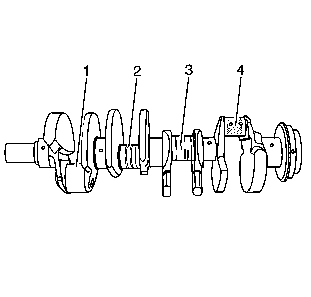
| • | Crankshaft journals (1) should be smooth with no evidence of scoring or damage |
| • | Scratches or uneven wear (3) |
| • | Wear or damage to the thrust journal surfaces |
| • | Scoring or damage to the rear seal surface |
| • | Restrictions to oil passages |
| • | Damage to threaded bolt holes |
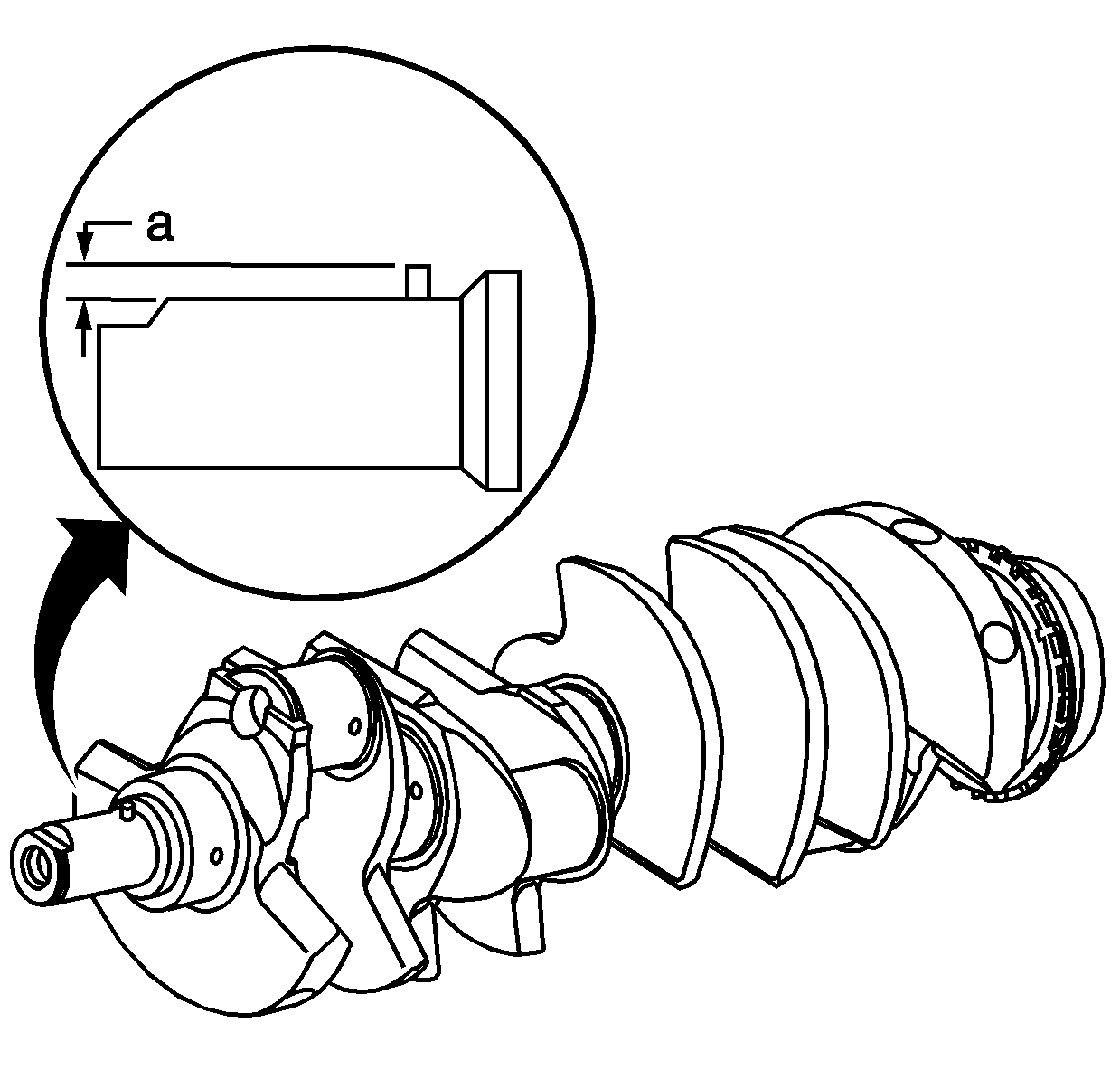
Important: The crankshaft pin is a pressed-in-place roll pin. The pin only needs to be removed from the crankshaft if the pin is damaged.
- Inspect the crankshaft pin for damage:
| • | Measure for proper installed height (a). Correct height should be 2.00-2.25 mm (0.078-0.088 in). |
| • | Replace the crankshaft pin if it is damaged. |
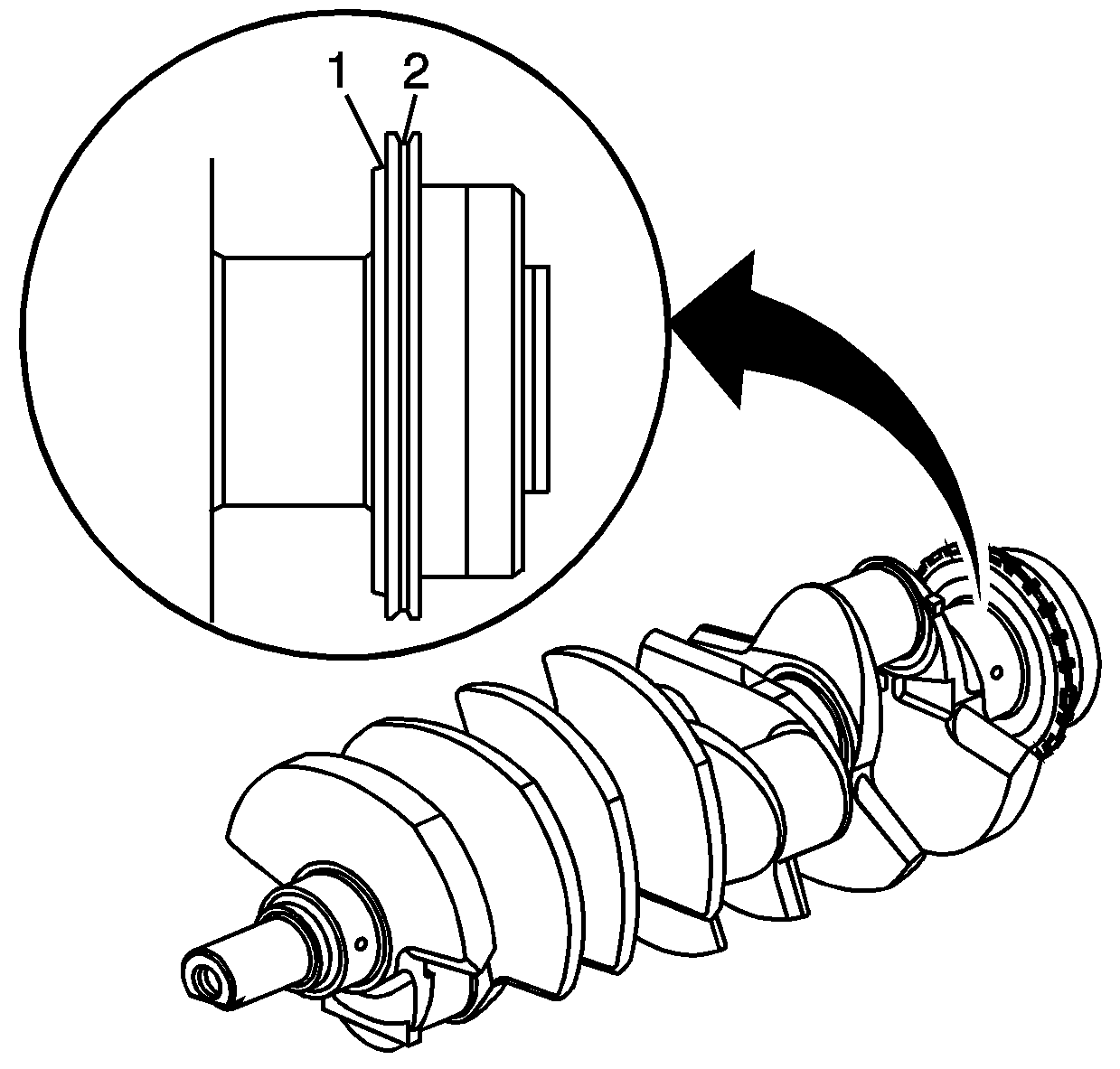
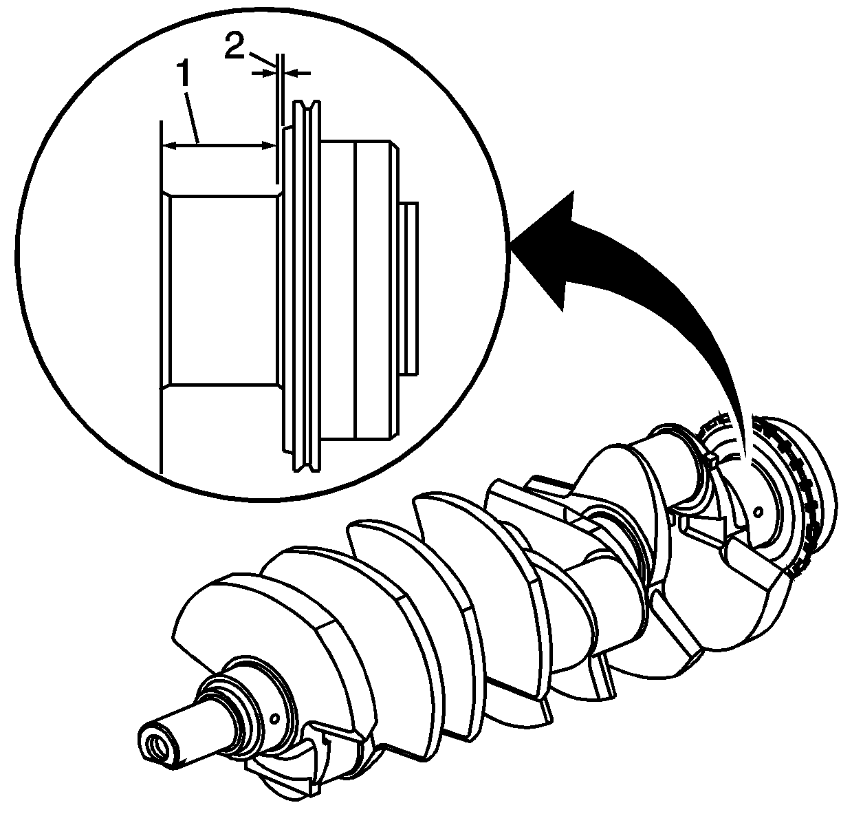
Important: Do NOT attempt to remove the crankshaft reluctor wheels. If the reluctor wheels are damaged and/or removed, the crankshaft must be replaced.
- Inspect the reluctor wheels for cracked, bent, or broken teeth.
| • | Measure between the crankshaft shoulder and the front reluctor wheel (1). |
| • | Measure the gap between the front and rear reluctor wheels (2). The maximum allowable gap is 0.15 mm (0.006 in). |
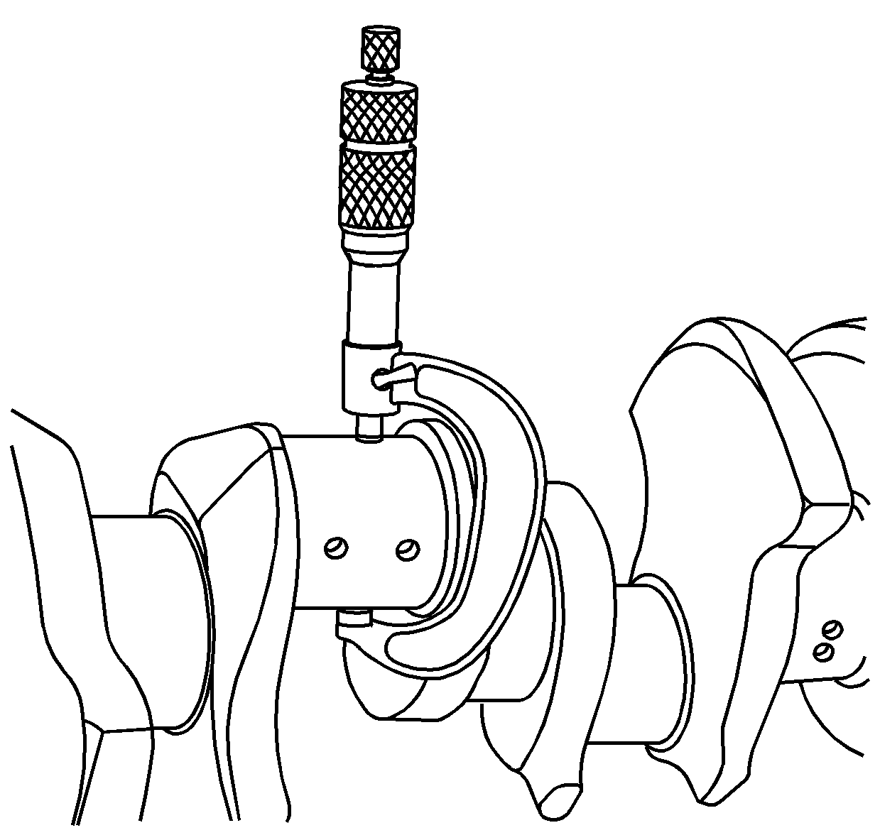
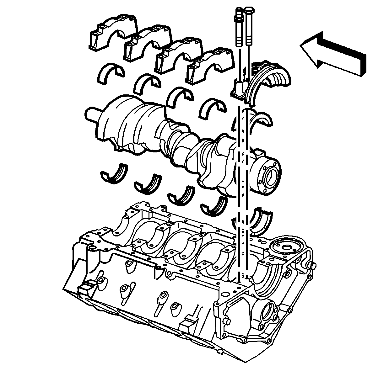
- Measure the crankshaft main journals and the crankpins for out-of-round and taper.
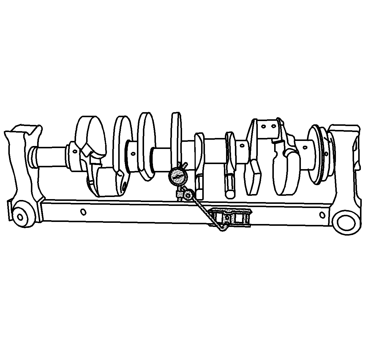
- Using a suitable fixture, support the crankshaft.
- Measure the crankshaft runout using the
J 7872
. Crankshaft runout should not exceed 0.051 mm (0.002 in).
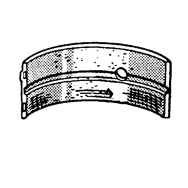
- Inspect the crankshaft thrust wall surface (1) for wear and/or excessive
runout (2). Refer to
Engine Mechanical Specifications
.
Crankshaft and Connecting Rod Bearing Inspection
Important: The crankshaft and connecting rod bearings should be inspected only to determine what kind of damage or failure has occurred. Always install NEW bearings once the bearings have been removed.
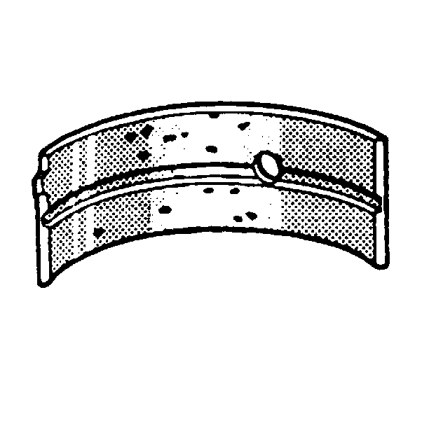
- Inspect the bearings for craters or pockets. Flattened sections on the bearing halves also indicate fatigue.
- Inspect the bearings for excessive scoring or discoloration.
- Inspect the bearings for dirt or debris embedded into the bearing material.
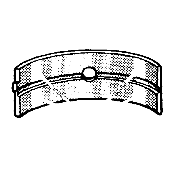
- Inspect the bearings for improper seating indicated by bright, polished sections of the bearings.
Crankshaft and Connecting Rod Bearing Clearance Measurement
The crankshaft and connecting rod bearings are of the precision insert type and do not use shims for adjustment.
Crankshafts with journals that measure less than minimum specifications must be replaced.
Micrometer Method for Crankshaft Bearings
Important: When bearings are removed, NEW bearings must be installed during reassembly.
- Measure the crankshaft main journal diameter with a micrometer in several places along the length, approximately 90 degrees apart, a minimum of 4 places. Average the measurements.
- Determine the taper and the out-of-round. Refer to
Engine Mechanical Specifications
.
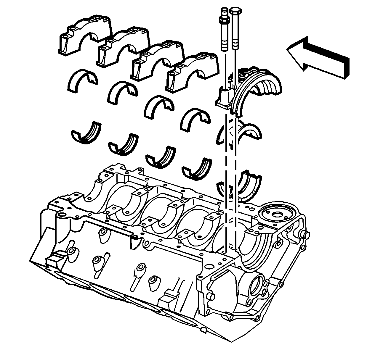
- Install the NEW crankshaft bearings into the crankshaft bearing caps and the engine
block.
Notice: Refer to Fastener Notice in the Preface section.
Important: Tighten the crankshaft bearing cap bolts before tightening the crankshaft bearing cap studs.
- Install the bearing cap bolts and studs.
Tighten
- Tighten the bearing cap bolts a first pass to 30 N·m (22 lb ft).
- Tighten the bearing cap studs a first pass to 30 N·m (22 lb ft).
- Tighten the bearing cap bolts a final pass an additional 90 degrees using the
J 45059
.
- Tighten the bearing cap studs a final pass an additional 80 degrees using the
J 45059
.
- Measure the crankshaft bearing inside diameter (ID), using an inside micrometer. Measure at a minimum of 4 places. Average the measurements.
- In order to determine the crankshaft bearing clearance, subtract the crankshaft journal diameter from the crankshaft bearing ID.
- Compare the crankshaft bearing clearance to the specifications. Refer to
Engine Mechanical Specifications
.
- If the crankshaft bearing clearances exceeds specifications, install undersize crankshaft bearings to achieve the correct clearance.
- Measure the new crankshaft bearing ID, using an inside micrometer.
- Replace the crankshaft if the proper clearances cannot be obtained with standard size bearings.
Micrometer Method for Connecting Rod Bearings
Important: When bearings are removed, NEW bearings must be installed during reassembly.
- Measure the crankpin diameter with a micrometer in several places along the length, approximately 90 degrees apart, a minimum of 4 places. Average the measurements.
- Determine the taper and the out-of-round. Refer to
Engine Mechanical Specifications
.
- Install the NEW connecting rod bearings into the connecting rod cap and the connecting rod.
Notice: Refer to Fastener Notice in the Preface section.
Important: Use the original connecting rod nuts for clearance measurement. During final assembly new connecting rod nuts must be used to obtain correct fastener tightening.
- Install the connecting rod cap and the original nuts.
Tighten
- Tighten the connecting rod nuts a first pass to 30 N·m (22 lb ft).
- Tighten the connecting rod nuts a final pass an additional 90 degrees, using the
J 45059
.
- Measure the connecting rod bearing ID, using an inside micrometer.
- Compare the connecting rod bearing clearance specifications. Refer to
Engine Mechanical Specifications
.
- If the connecting rod bearing clearances exceed specifications, replace components, as required.
Plastic Gage Method for Crankshaft Bearings
Important: When bearings are removed, NEW bearings must be installed during assembly.
- Install the crankshaft and the new crankshaft bearings into the block. Do not damage the crankshaft reluctor rings.
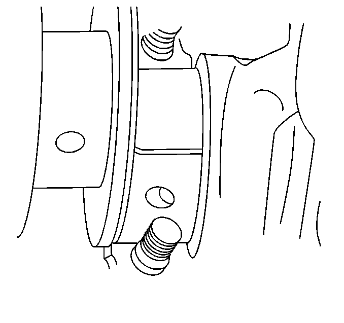
- Install the gaging plastic the full width of the crankshaft journal.
Notice: Refer to Fastener Notice in the Preface section.
Important: Tighten the inner crankshaft bearing cap bolts before tightening the outer crankshaft bearing cap studs. The crankshaft journal and the crankshaft bearing surface must be free from oil in order to obtain a correct measurement.
Do not allow the crankshaft to rotate while performing the measurement, or an incorrect measurement will be obtained.
- Install the bearing cap bolts and studs.
Tighten
- Tighten the bearing cap bolts a first pass to 30 N·m (22 lb ft).
- Tighten the bearing cap studs a first pass to 30 N·m (22 lb ft).
- Tighten the bearing cap bolts a final pass an additional 90 degrees, using the
J 45059
.
- Tighten the bearing cap studs a final pass an additional 80 degrees, using the
J 45059
.
- Remove the crankshaft bearing cap bolts and the crankshaft bearing caps. The gaging plastic may adhere to either the crankshaft journal or the crankshaft bearing surfaces.
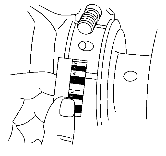
- On the edge of the gaging plastic envelope there is a graduated scale. Without
removing the gaging plastic, measure the compressed width at the widest point.
- If the flattened gaging plastic tapers toward the middle or toward the end, there may be a difference in clearance indicating taper, low spot, or other irregularity of the crankshaft bearing or the crankshaft journal.
| • | Normally the crankshaft journals wear evenly and are not out-of-round. However, if a crankshaft bearing is being fitted to an out-of-round 0.0254 mm (0.001 in) maximum crankshaft journal, ensure to fit to the maximum diameter of the
crankshaft journal. |
| • | If the crankshaft bearing is fitted to the minimum diameter and the crankshaft journal is excessively out-of-round, the interference between the crankshaft bearing and the crankshaft journal will result in rapid crankshaft bearing failure. |
- Compare the crankshaft bearing clearance to the specifications. Refer to
Engine Mechanical Specifications
.
- If the crankshaft bearing clearances exceeds specifications, replace components, as required.
- Measure the new crankshaft bearing ID, using the same method.
- Replace the crankshaft if the proper clearances cannot be obtained with standard size bearings.
- Remove the flattened gaging plastic.
- Measure the remaining crankshaft journals.
Plastic Gage Method for Connecting Rod Bearings
Important: When bearings are removed, NEW bearings must be installed during assembly.
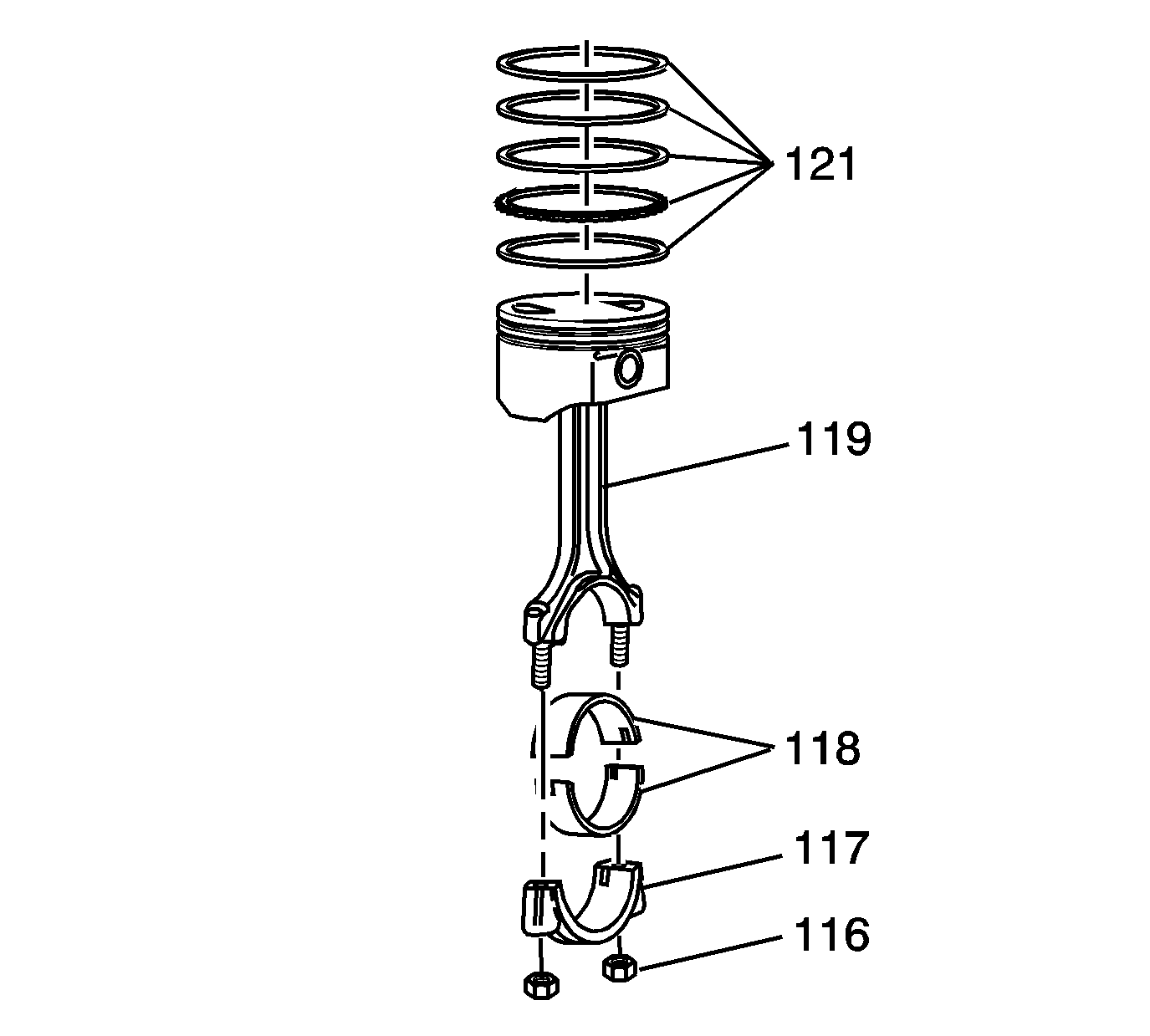
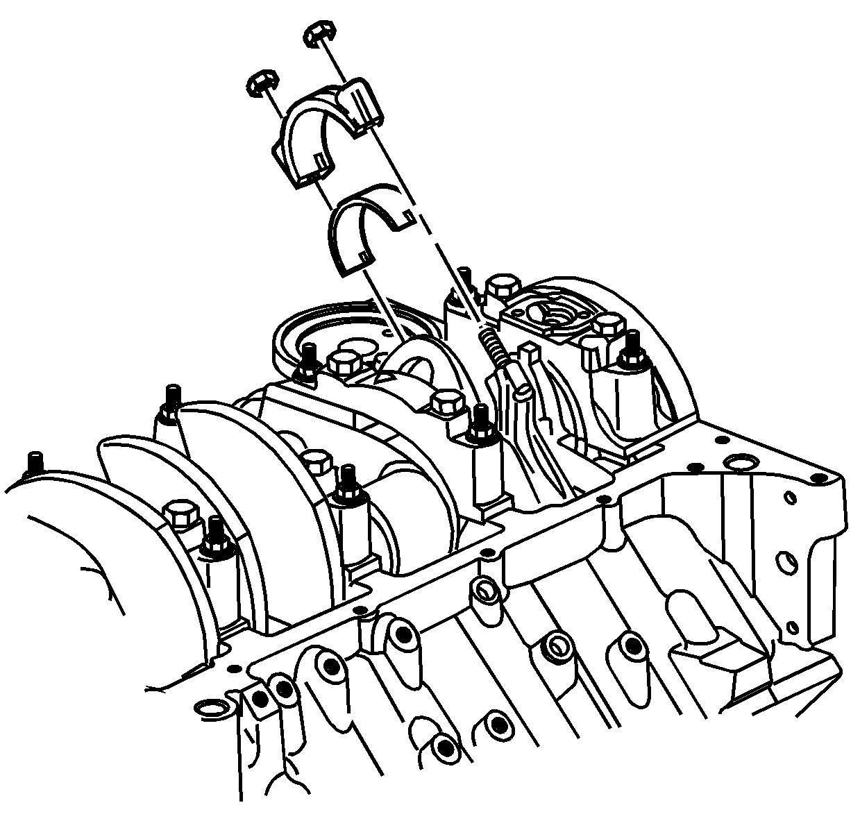
- Install the connecting rod bearings (118) into the connecting rod (119) and the connecting rod cap (117).
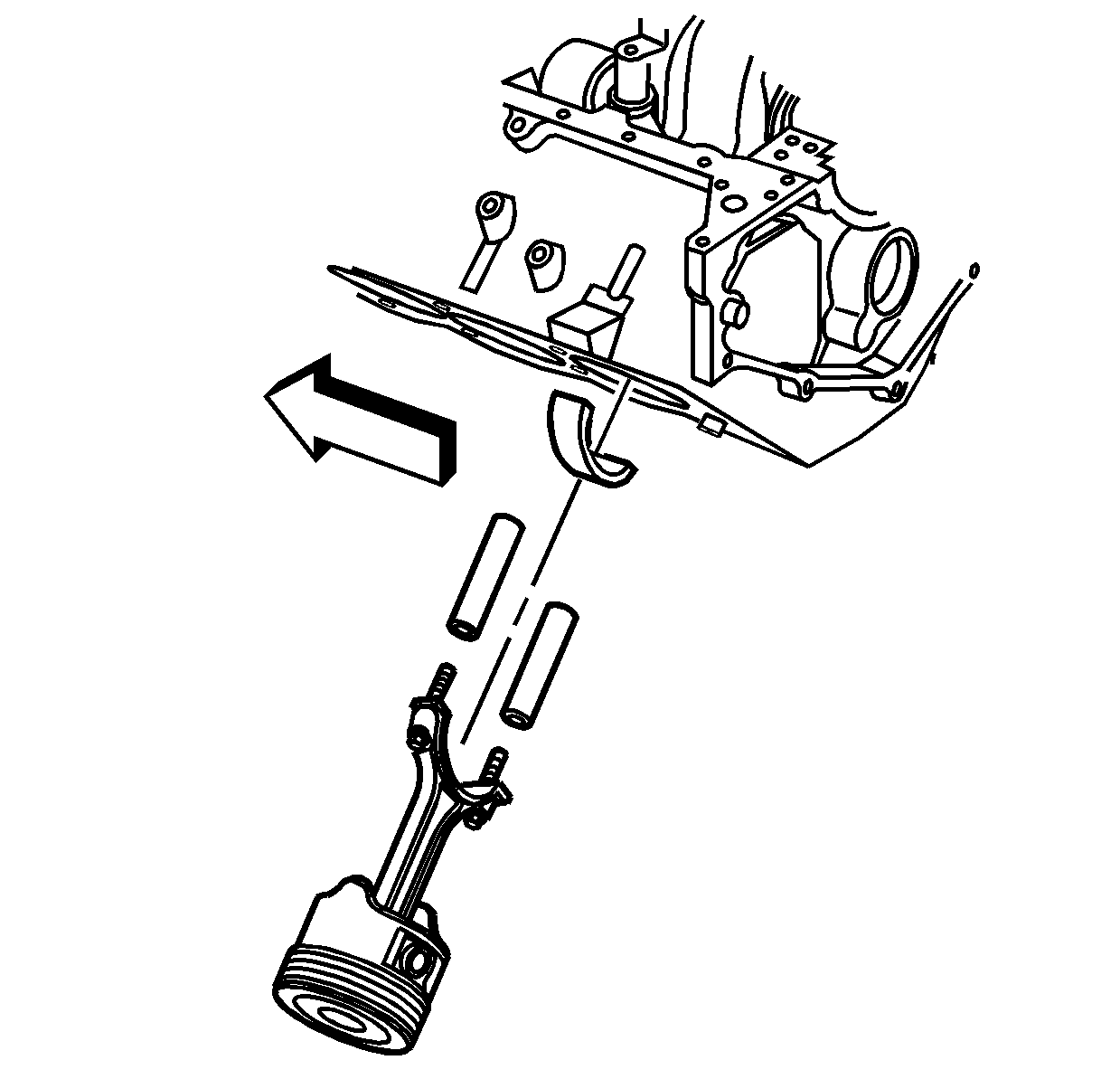
- Using rubber fuel line (1) over the connecting
rod bolts, install the piston and connecting rod assembly onto the crankpin journal.
- Install the gaging plastic the full width of the crankpin journal.
Notice: Refer to Fastener Notice in the Preface section.
Important:
| • | Use the original connecting rod nuts for clearance measurement. |
| • | During final assembly, NEW connecting rod nuts must be used in order to obtain correct fastener tightening. |
- Install the connecting rod cap and the original nuts.
Tighten
- Tighten the connecting rod nuts a first pass to 30 N·m (22 lb ft).
- Tighten the connecting rod nuts a final pass an additional 90 degrees, using the
J 45059
.
- Remove the connecting rod nuts and cap. The gaging plastic may adhere to either the crankpin journal or the connecting rod bearing surface.
- There is a graduated scale on the edge of the gaging plastic envelope. Without
removing the gaging plastic, measure the compressed width at the widest point.
If the flattened gaging plastic tapers toward the middle or toward the end, there may be a difference in clearance, indicating taper, low spot, or other irregularity of
the crankshaft bearing or the crankpin journal.
- Normally the crankpin journals wear evenly and are not out-of-round. However, if a connecting rod bearing is being fitted to an out-of-round 0.0254 mm (0.001 in) maximum crankpin journal, ensure to fit to the maximum diameter of the
crankpin journal. If the connecting rod bearing is fitted to the minimum diameter and the crankpin journal is excessively out-of-round, the interference between the connecting rod bearing and the crankpin journal will result in rapid connecting rod bearing failure.
- Compare the connecting rod bearing clearance to the specifications. Refer to
Engine Mechanical Specifications
.
- If the connecting rod bearing clearances exceed specifications, replace components, as required.
- Remove the flattened gaging plastic.
- Measure the remaining crankpin journals.
Measuring Crankshaft End Play
Important: In order to properly measure the crankshaft end play, the crankshaft, bearings, bearing caps, and fasteners must be installed into the engine block and the bolts tightened to specifications. Refer to
Crankshaft and Bearing Installation
.
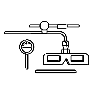
- Install the
J 7872
, or equivalent, to the cylinder block, with the dial indicator plunger against one of the counterweights of the crankshaft.
- Firmly thrust the end of the crankshaft first rearward then forward. This lines up the rear crankshaft bearing and the crankshaft thrust surfaces.
- With the crankshaft pushed forward, zero the dial indicator. Move the crankshaft rearward and read the end play measurement on the dial indicator. An optional method is to insert a feeler gage between the crankshaft and the bearing surface and measure
the clearance. Refer to
Engine Mechanical Specifications
.
- If the correct end play cannot be obtained, inspect the crankshaft thrust wall surface or surfaces for wear and/or excessive runout.
- Turn the crankshaft in order to inspect for binding. If the crankshaft does not turn freely, loosen the crankshaft bearing bolts and studs, 1 cap at a time, until the tight bearing is located. The following conditions could cause a lack of
clearance at the bearing:
| • | Burrs on the crankshaft bearing cap |
| • | Foreign matter between the crankshaft bearing and the block or the crankshaft bearing cap |
| • | A faulty crankshaft bearing |
Measuring Connecting Rod Side Clearance
Important: In order to properly measure the connecting rod side clearance, the piston/connecting rod assembly and bearings must be installed into the engine block and the connecting rod nuts tightened to specifications. Refer to
Piston, Connecting Rod, and Bearing Installation
.
- Install the
J 7872
, or equivalent, to the cylinder block, with the dial indicator plunger against the side of the pair of connecting rods.
- With the connecting rods pushed forward, zero the dial indicator. Firmly move the pair of connecting rods side to side and read the measurement on the dial indicator. An optional method is to insert a feeler gage between the connecting rod caps and
measure the connecting rod side clearance. Refer to
Engine Mechanical Specifications
.
Measuring Connecting Rod Bearing Clearance - Using J 43690/J 43690-100
The
J 43690
and
J 43690-100
have been developed as a more accurate method to measure connecting rod bearing clearances. The instructions below provide
an overview of tool set-up and usage. For more detailed information, refer to the tool manufacturers instruction sheets.
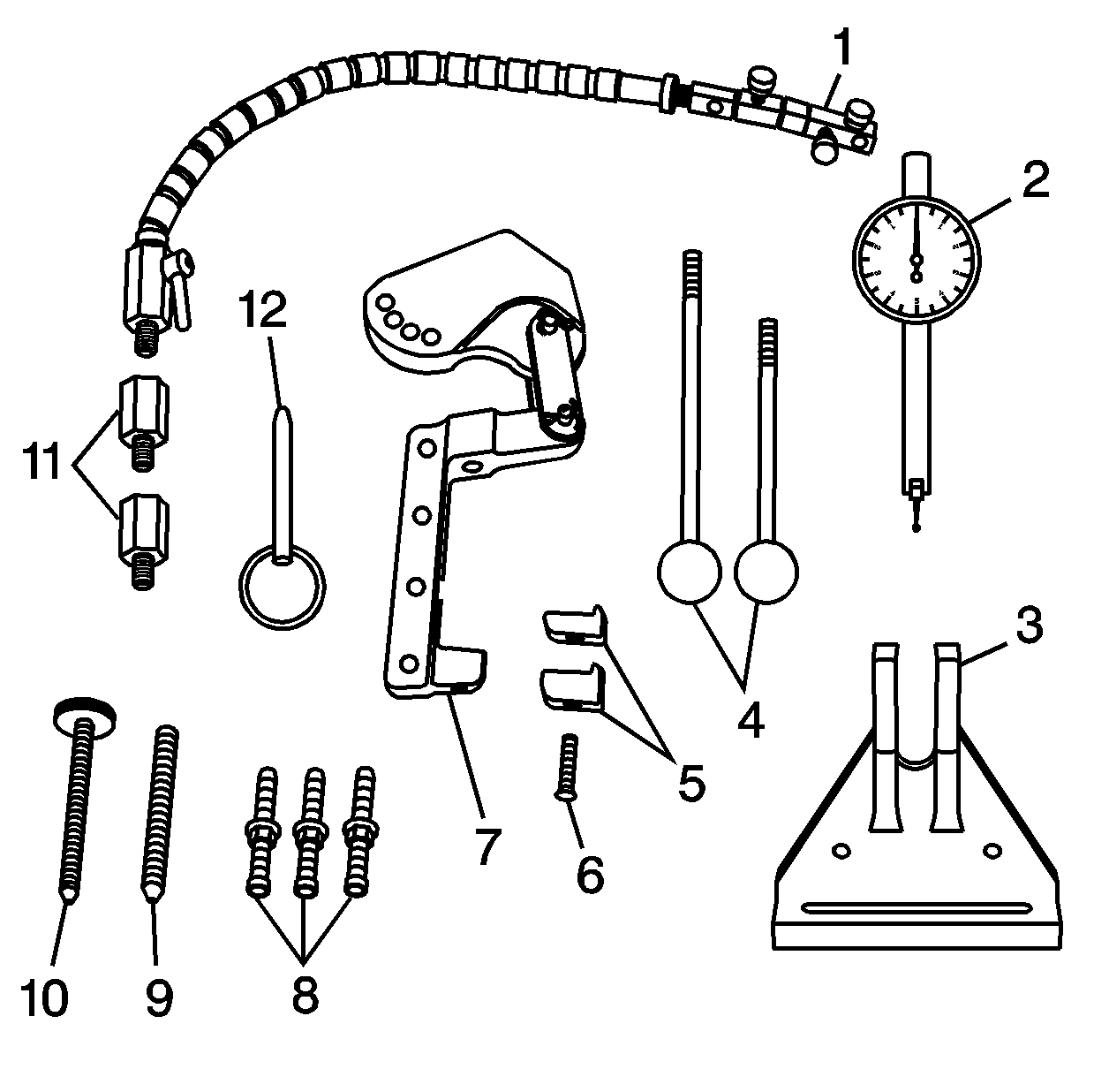
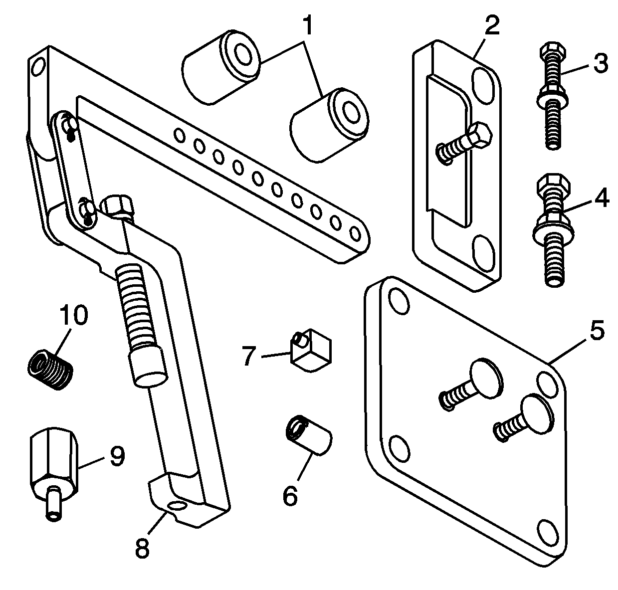
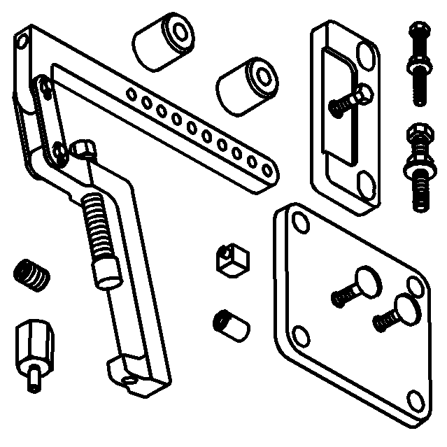
J 43690 Rod Bearing Clearance Checking Tool
| • | J 43690-20 Swivel Base (1) |
| • | J 43690-19 Dial Indicator (2) |
| • | J 43690-5, J 43690-6 Handle (4) |
| • | J 43690-10, J 43690-11 Foot (5) |
| • | J 43690-1 Pivot Arm Assembly (7) |
| • | J 43690-3, J 43690-7, J 43690-8 Screws (8) |
| • | J 43690-17, J 43690-18 Adapter (11) |
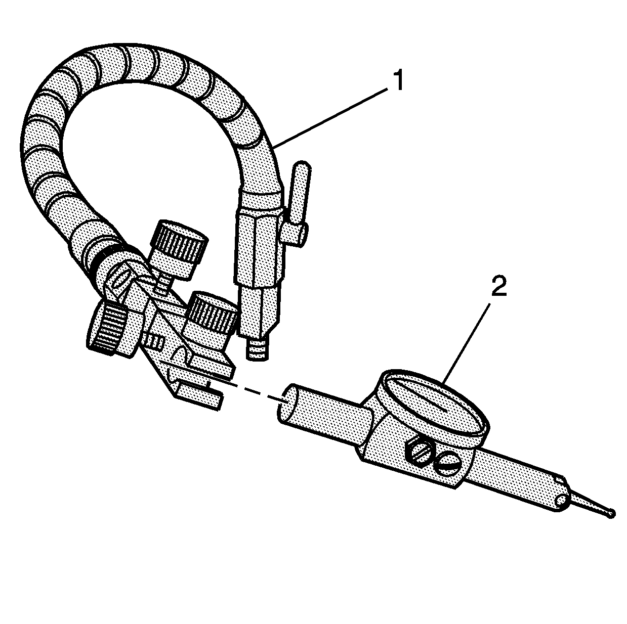
J 43690-100 Rod Bearing Clearance Checking Tool - Adapter Kit
| • | J 43690-105 Retainer Plate (2) |
| • | J 43690-106 Retainer Plate (5) |
| • | J 43690-101 Pivot Arm Assembly (8) |
| • | J 43690-103 Adapter (9) |
Important: The crankshaft must be secure, with no movement or rotation, in order to obtain an accurate reading.
- Rotate the crankshaft until the journal/connecting rod to be measured is in the 12 o'clock position.
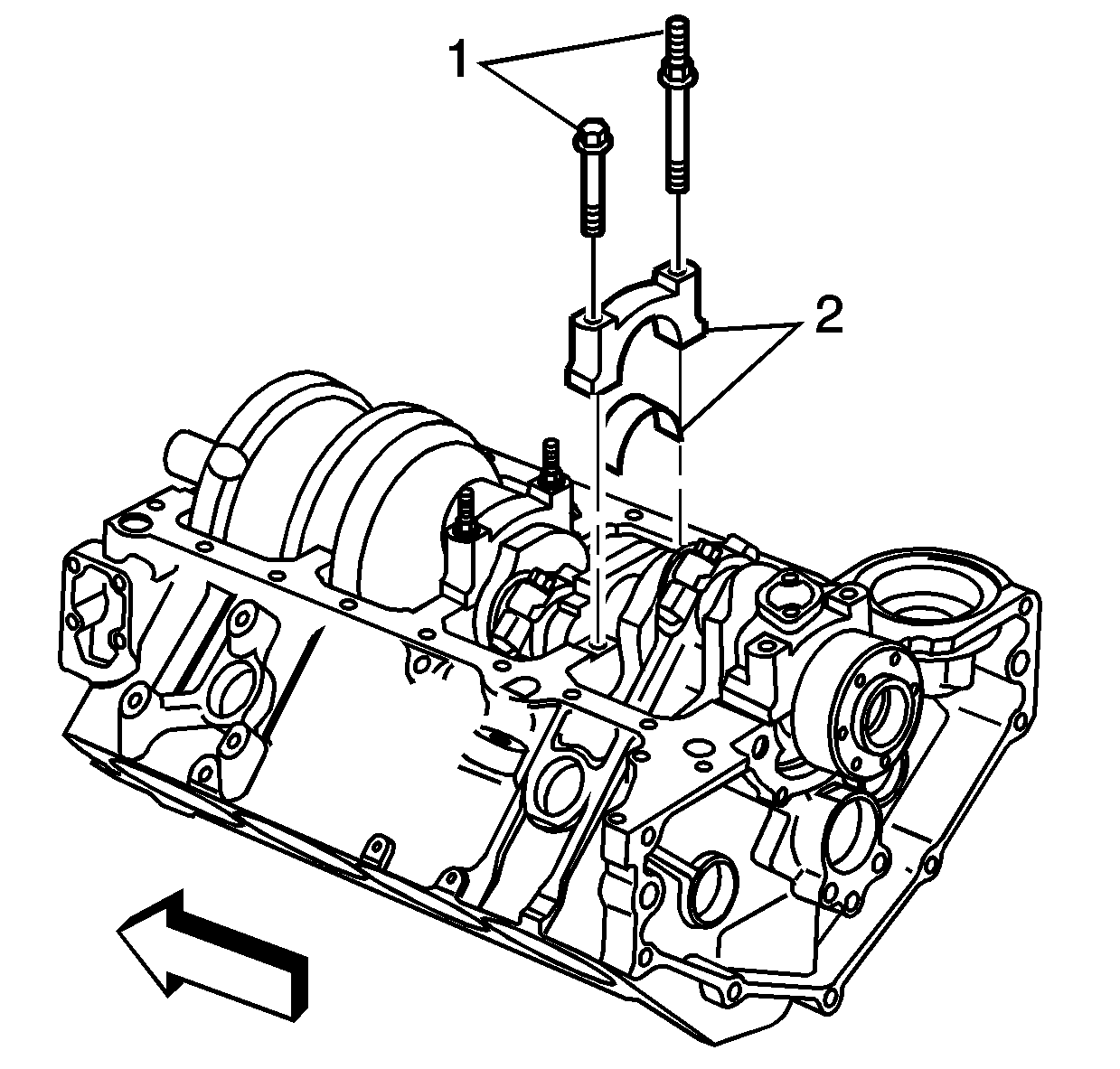
- Remove a bearing cap bolts (1).
- Remove the bearing half and bearing cap (2).
- Insert a piece of paper card stock onto the crankshaft journal.
- Install the bearing half and cap (2) and bolts (1). Refer to
Fastener Tightening Specifications
.
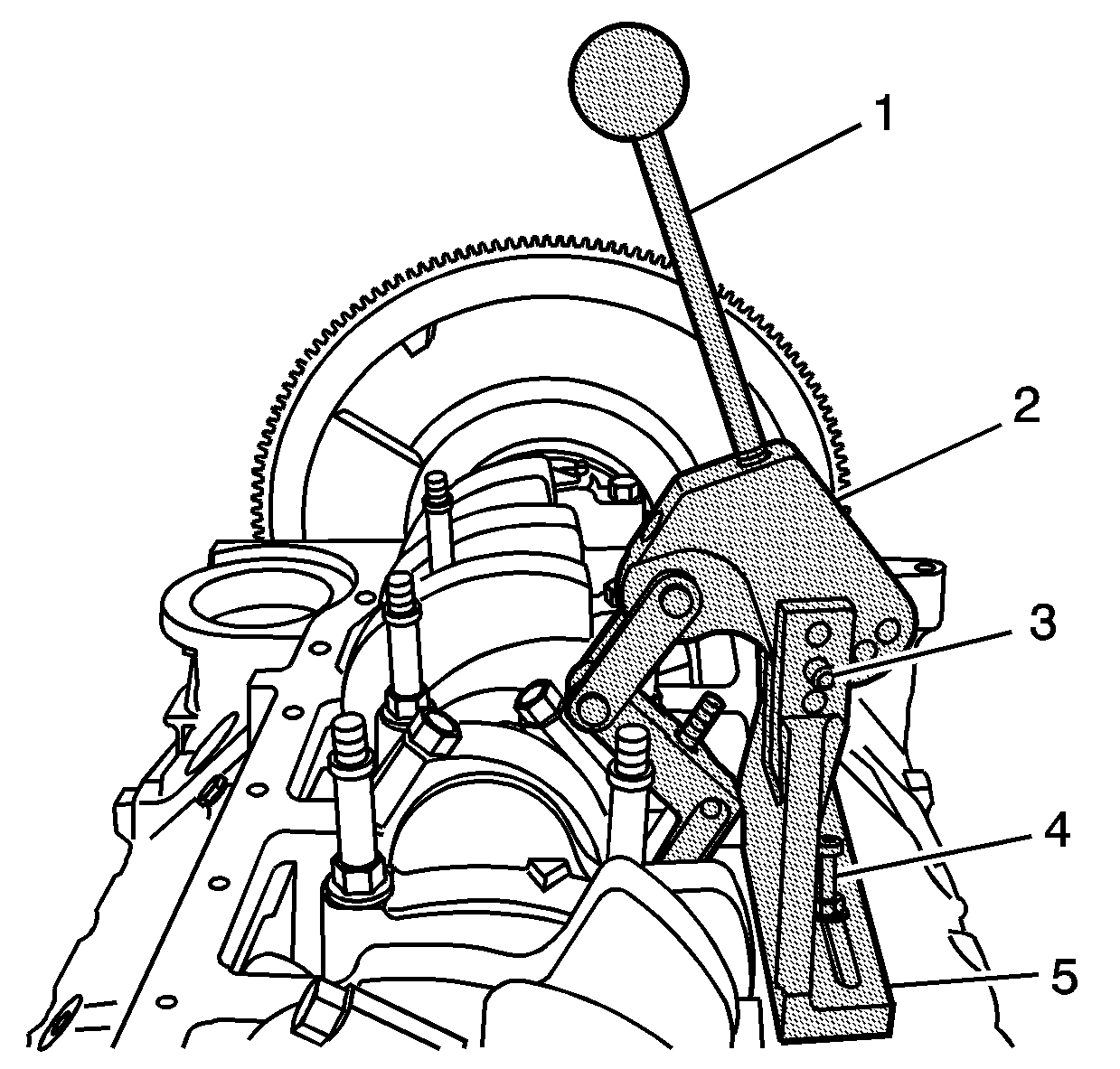
- Install the following tools:
- Install the swivel base (1) and dial indicator (2).
- Adjust, per the manufacturers instructions, and measure the connecting rod bearing clearance.
A connecting rod with a clearance in excess of 0.081 mm (0.0032 in) is considered excessive. Service components, as required.
