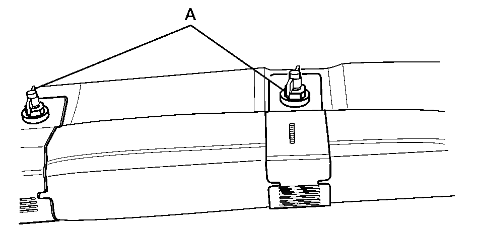
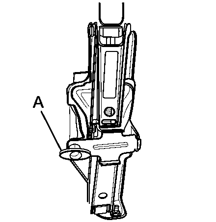
Regular Cab and Crew Cab (Except 1500 Crew Cab)
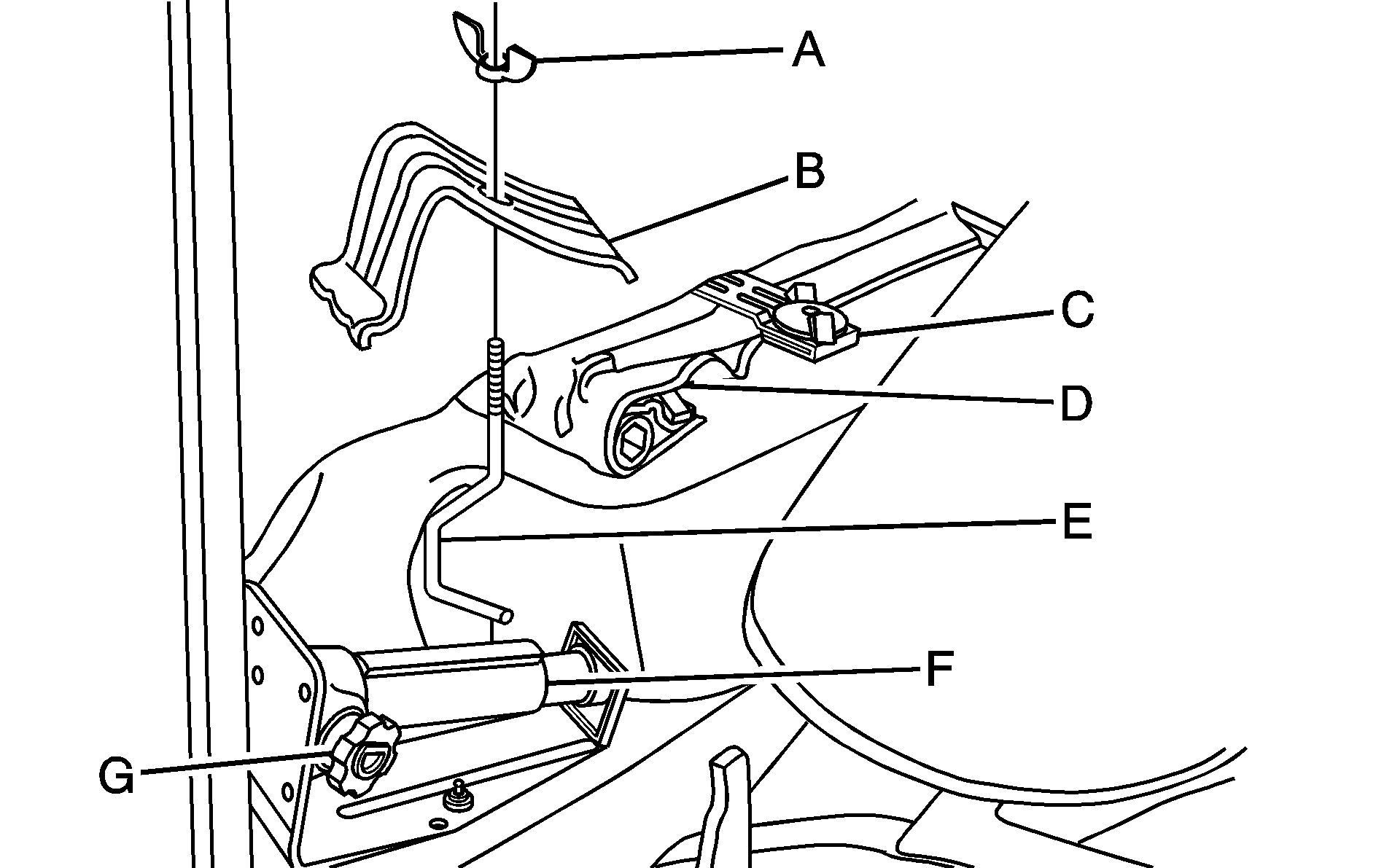
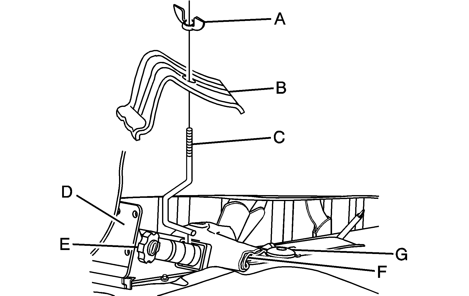
Wing Nut Holding Wheel Blocks
Wheel Blocks
Retaining Bracket and Wing Nut
Tool Kit and Jack Tools
Retaining Hook
Jack
Knob
Extended Cab
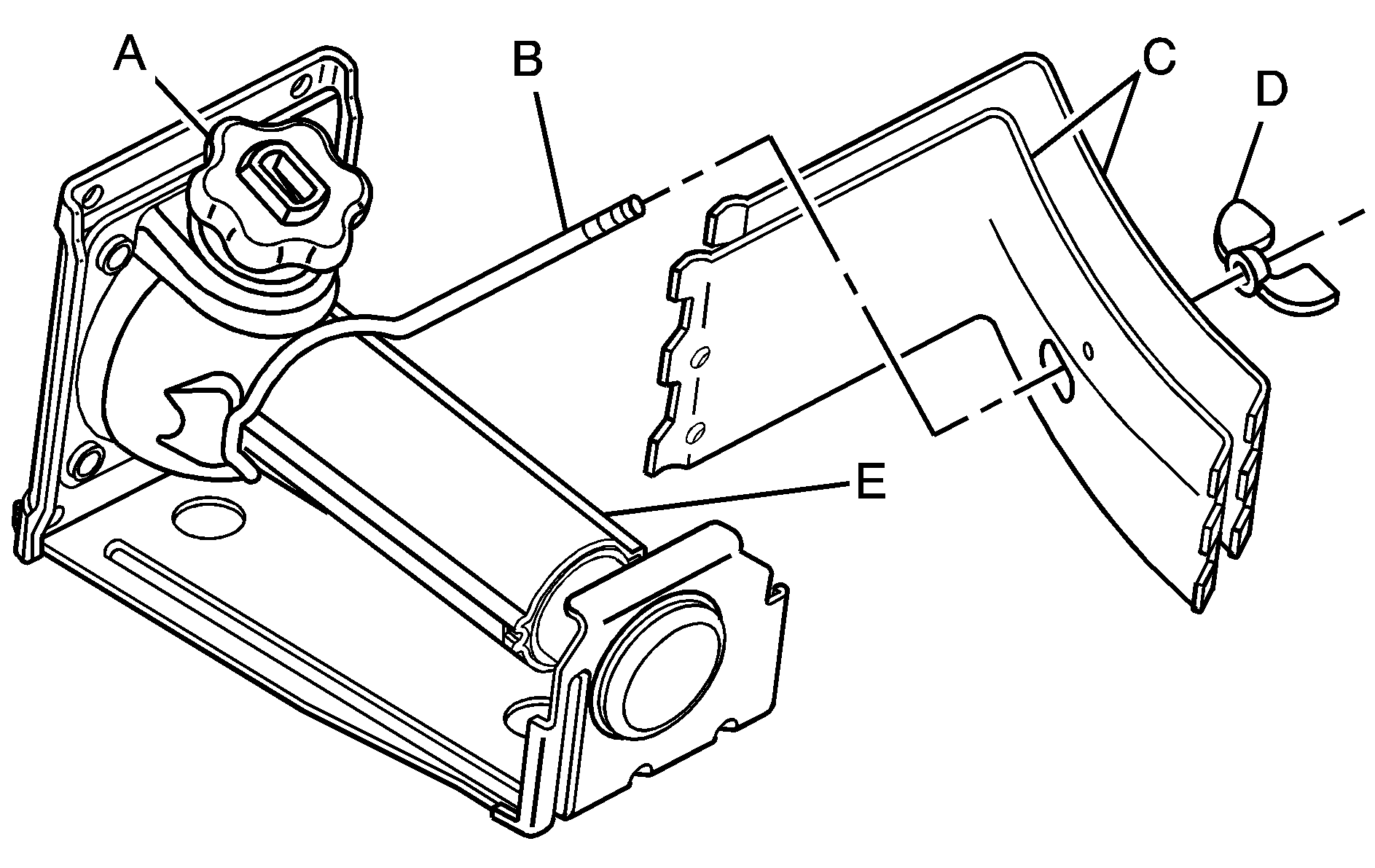
Wing Nut Holding Wheel Blocks
Wheel Blocks
Retaining Hook
Jack
Knob
Retaining Bracket and Wing Nut
Tool Kit and Jack Tools
1500 Crew Cab
Knob
Retaining Hook
Wheel Blocks
Wing Nut Holding Wheel Blocks
Jack
For regular cab models, the equipment you will need is behind the passenger's seat. For extended and crew cab models, the equipment is on the shelf behind the passenger's side second row seat.
- If there is a cover, move the seats forward and turn the wing nut on the cover counterclockwise to remove it. For crew cab models, pull up the second row seat with the loop at the base of the seat cushion to access the tools.
- Turn the knob on the jack counterclockwise to lower the jack head to release the jack from its holder.
- Remove the wheel blocks and the wheel block retainer by turning the wing nut counterclockwise.
- Remove the wing nut used to retain the storage bag and tools by turning it counterclockwise.
You will use the jack handle extensions and the wheel wrench to remove the underbody-mounted spare tire.
-
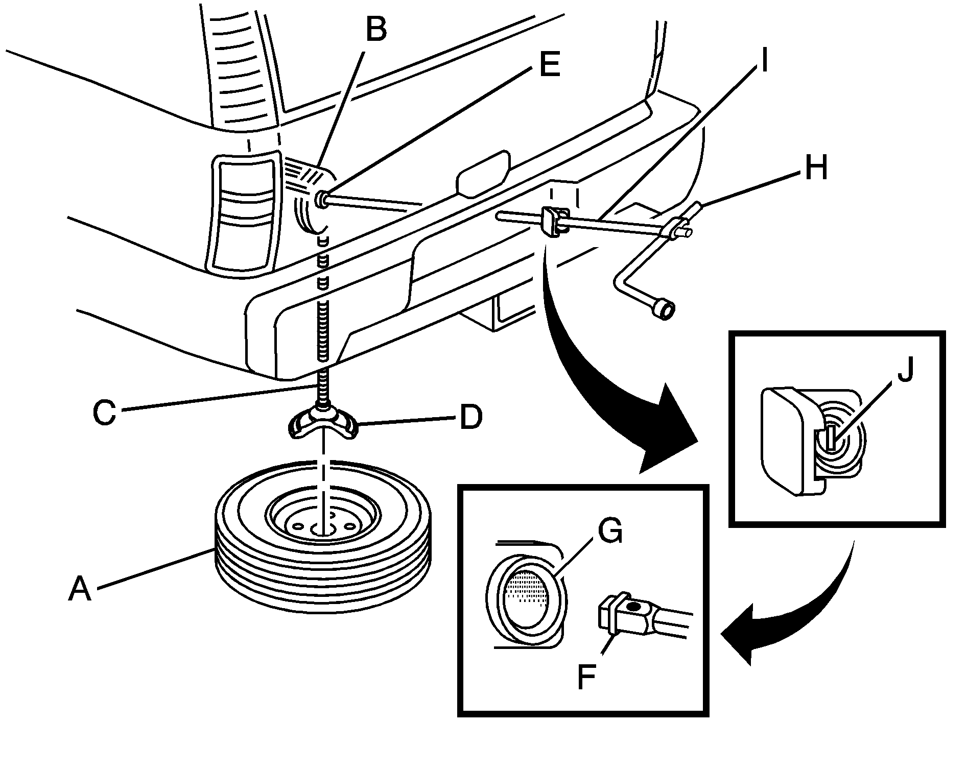
Spare Tire (Valve Stem Pointed Down)
Hoist Assembly
Hoist Cable
Tire Retainer
Hoist Shaft
Hoist End of Extension Tool
Hoist Shaft Access Hole
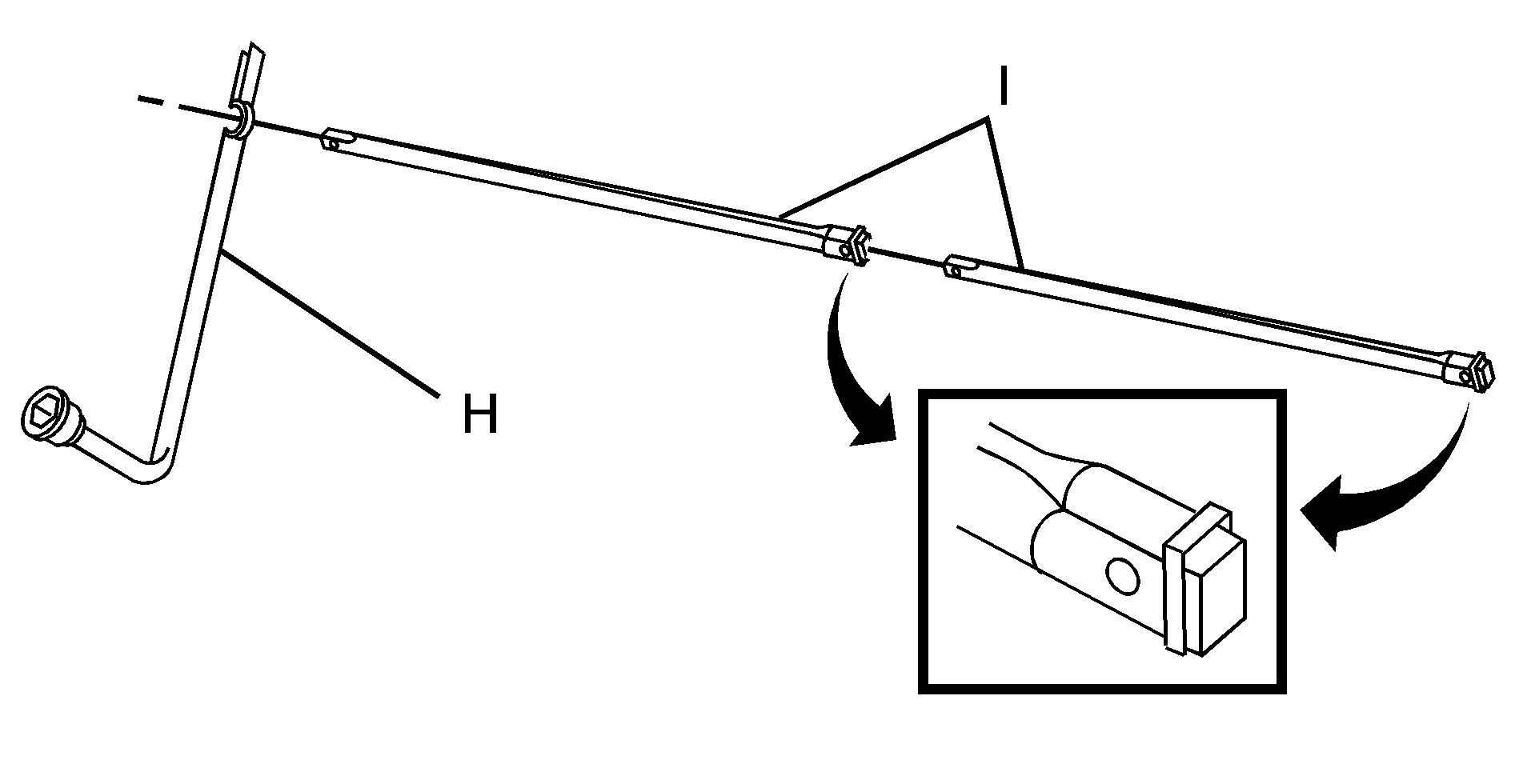
Wheel Wrench
Jack Handle Extensions
Spare Tire Lock (If Equipped)
- Open the spare tire lock cover on the bumper and use the ignition key to remove the lock, if equipped with a spare tire lock (J).
- Assemble the wheel wrench (H) and the two jack handle extensions (I) as shown.
- Be sure the hoist end of the extension connects to the hoist shaft (E). The ribbed square end of the extension is used to lower the spare tire.
- Turn the wheel wrench (H) counterclockwise to lower the spare tire to the ground. Continue to turn the wheel wrench until the spare tire can be pulled out from under the vehicle.
- Put the spare tire near the flat tire.
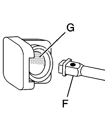
Insert the hoist end (open end) (F) of the extension through the hole (G) in the rear bumper.
If the spare tire does not lower to the ground, the secondary latch is engaged causing the tire not to lower. See Secondary Latch System .
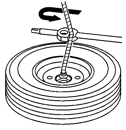
Use the wheel wrench hook which allows you to pull the hoist cable towards you to assist in reaching the spare tire.
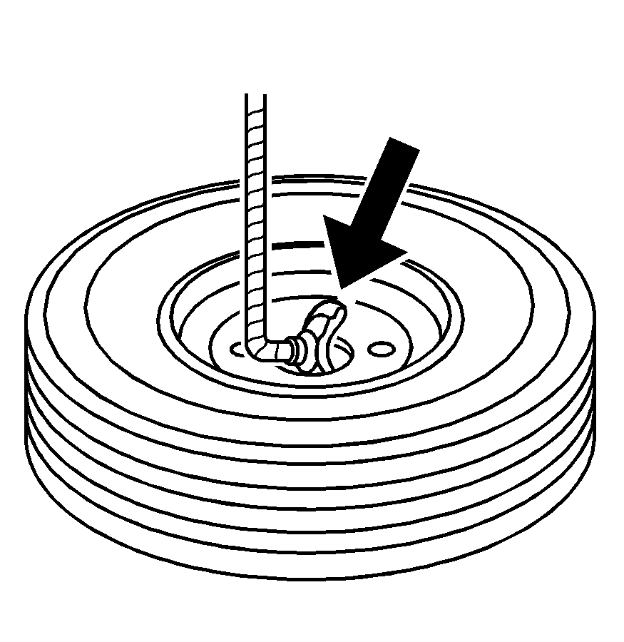
Tilt the retainer at the end of the cable when the tire has been lowered, so it can be pulled up through the wheel opening.
Maintenance Body
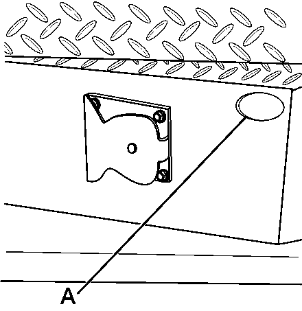
The heavy duty bumper of the vehicle has an opening (A) to gain access to the spare tire hoist. For more information refer to Changing a Flat Tire in the 2005 Vehicle Owner Manual.
Pickup Vehicles
Under Body Carrier
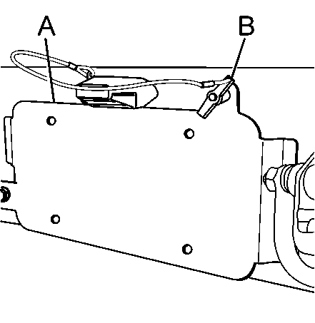
The heavy duty bumper of the vehicle has an opening in the bumper to gain access to the spare tire hoist. This opening is located behind the license plate mount. In order to gain access to this opening you must lower the license plate. To lower the plate you must remove the pin (B). Rotate the plate (A) down enough to access the opening. For more information refer to Changing a Flat Tire in the 2005 Vehicle Owner Manual.
Cargo Bed Carrier
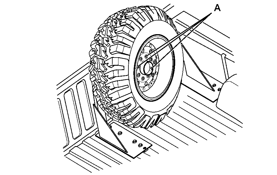
The cargo bed tire carrier is located in the passenger front of the cargo bed. To remove the tire, use and turn the wheel wrench counterclockwise and remove the wheel nuts (A).
Swing Away Carrier
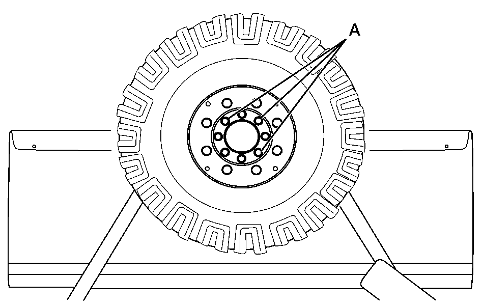
The swing away tire carrier is located at the rear of the vehicle attached to the bumper. To remove the tire, use and turn the wheel wrench counterclockwise and remove the wheel nuts (A).
To open the swing away spare tire carrier, do the following:
- Press the button on the pin (B), which is attached to the cable (A), to remove the pin from the latch bolt nut (C) .
- Lift up on the latch on the left side of the vehicle to release the spare tire carrier from the vehicle. The handle will stay in the raised position until the spare tire carrier is closed and latched properly.
- Swing the spare tire carrier to the side.
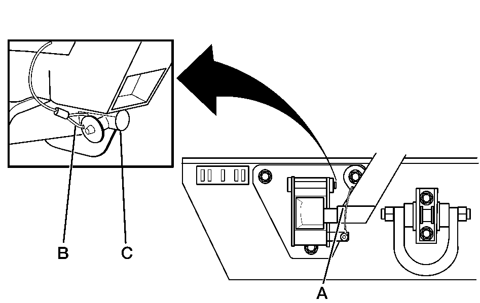
Caution: If you drive with the spare tire carrier unlatched, you could injure pedestrians or damage the vehicle. Make sure the carrier is secure before driving.
To close the swing away tire carrier, do the following:
- Move the spare tire carrier back into place until it latches, by closing it into the latch forcefully. The spare tire carrier is latched properly when the latch handle has lowered to the closed position.
- Reinstall the cable (A) by pushing in the button on the pin (B) and inserting the pin into the latch bolt nut.
- Pull on the spare tire carrier to make sure it is firmly latched.
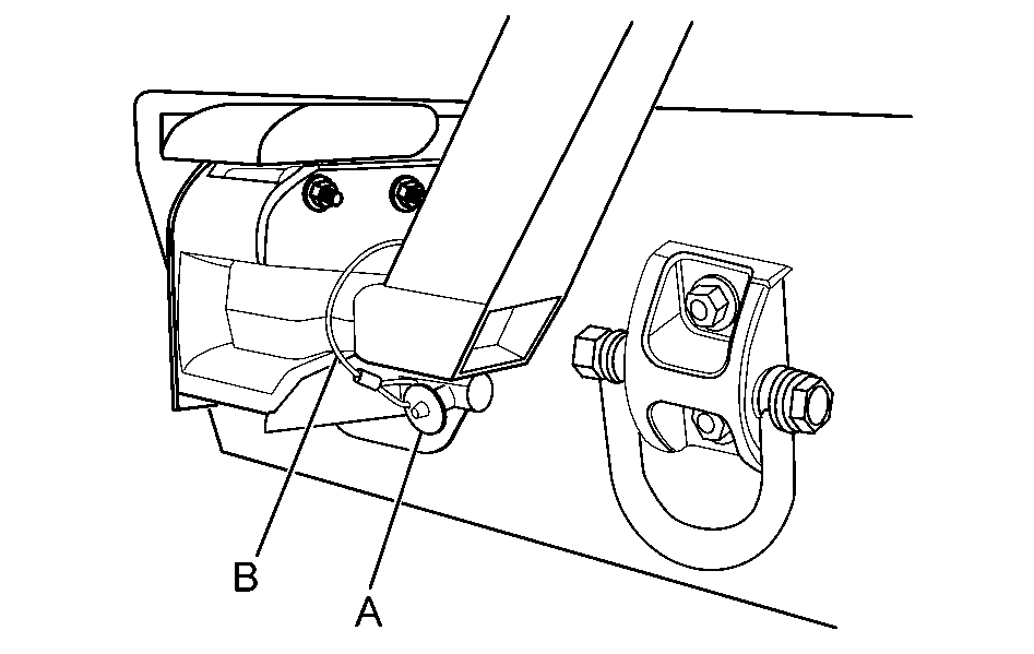
Caution: The spare tire carrier must be secured so that it does not strike and injure someone. Always close it into the latch forcefully. Make sure that the release handle is fully closed (down) and that the cable is attached.
In Vehicle Carrier
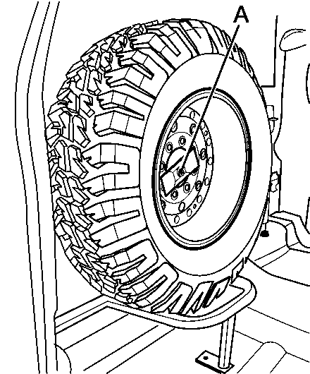
The in vehicle tire carrier is located behind the passenger seat. To remove the tire turn the nut (A) counterclockwise then remove the tire from the carrier.
Ambulance Body
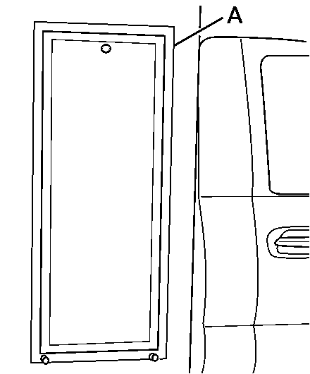
The spare tire is located on the right side front of the ambulance behind door (A). A key is required to open the door. The door is hinged at the bottom and swings down. A ramp is attached to the inside of the door to aid in removal and installation of the tire.
The following steps apply only to vehicles featuring Option Code EMP (Enhanced Mobility Package). For vehicles without EMP refer to the 2005 Vehicle Owner Manual.
For regular cab models, the jack you will need is behind the passenger’s seat.
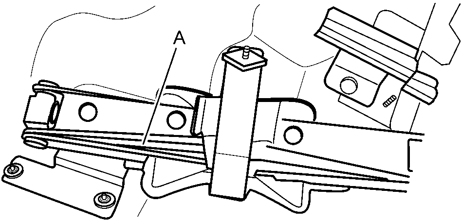
Jack
The equipment is behind the driver’s seat mounted on the floor.
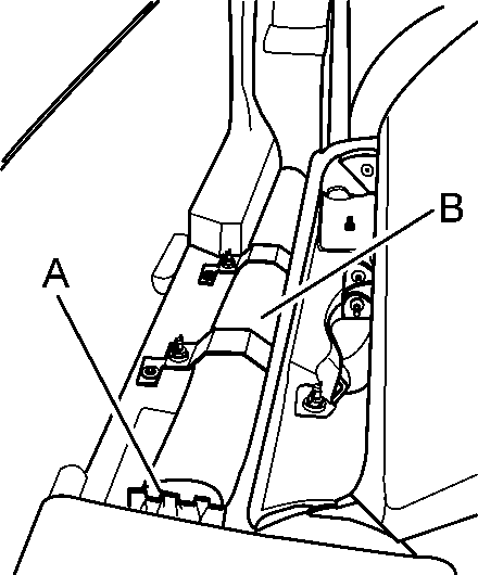
Wheel Blocks
Tire Tools
For extended cab models, the equipment you will need is under the passenger’s side second row seats.
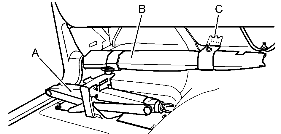
Jack
Tire Tools
Wheel Blocks
For crew cab models, the jack you will need is under the passenger’s side second row seats.
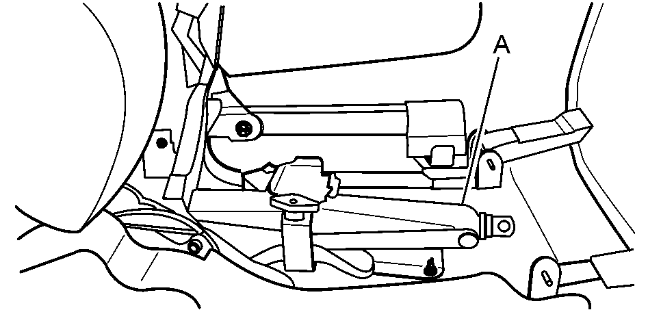
The equipment is under the shelf behind the driver’s side second row seats.

Wheel Blocks
Tire Tools
To Remove
- Wing nuts (A) are used to retain the storage bag and tools. To remove them, turn the wing nuts counterclockwise.
- Remove the wheel blocks by turning the wing nut counterclockwise.
- To release the jack from its holder, turn the knob (A) on the jack holder counterclockwise.
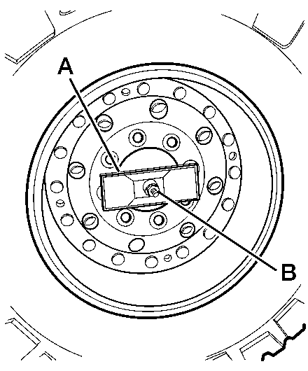
- Using the wheel wrench and ratchet, remove the retainer nut (B) and the retainer (A) or wheel nuts.
- Remove tire from the vehicle and put the spare tire near the flat tire.
