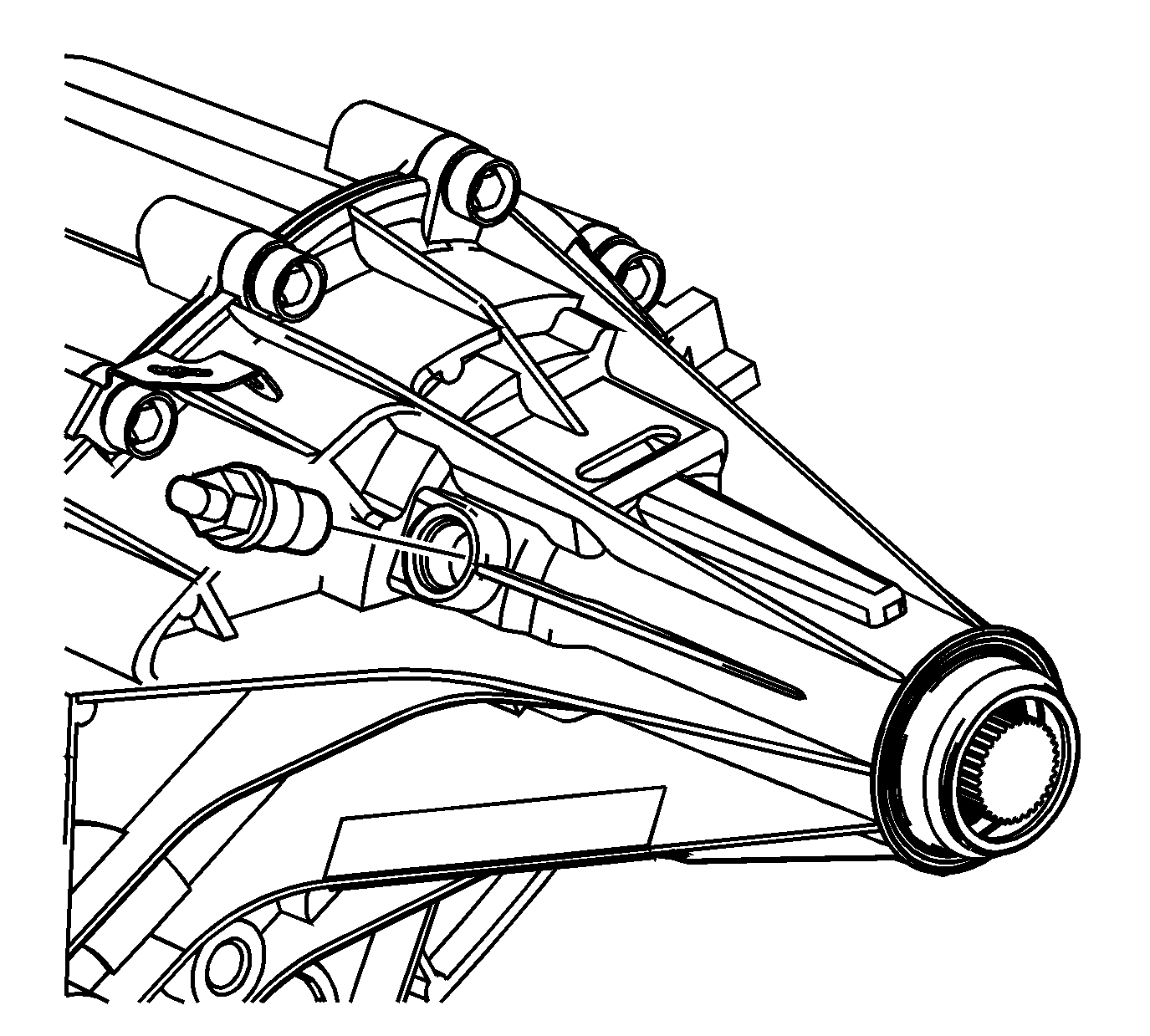
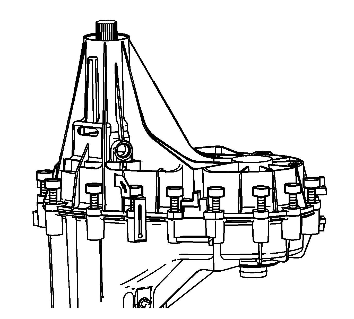
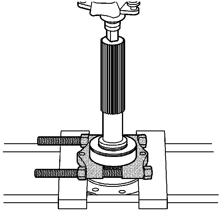
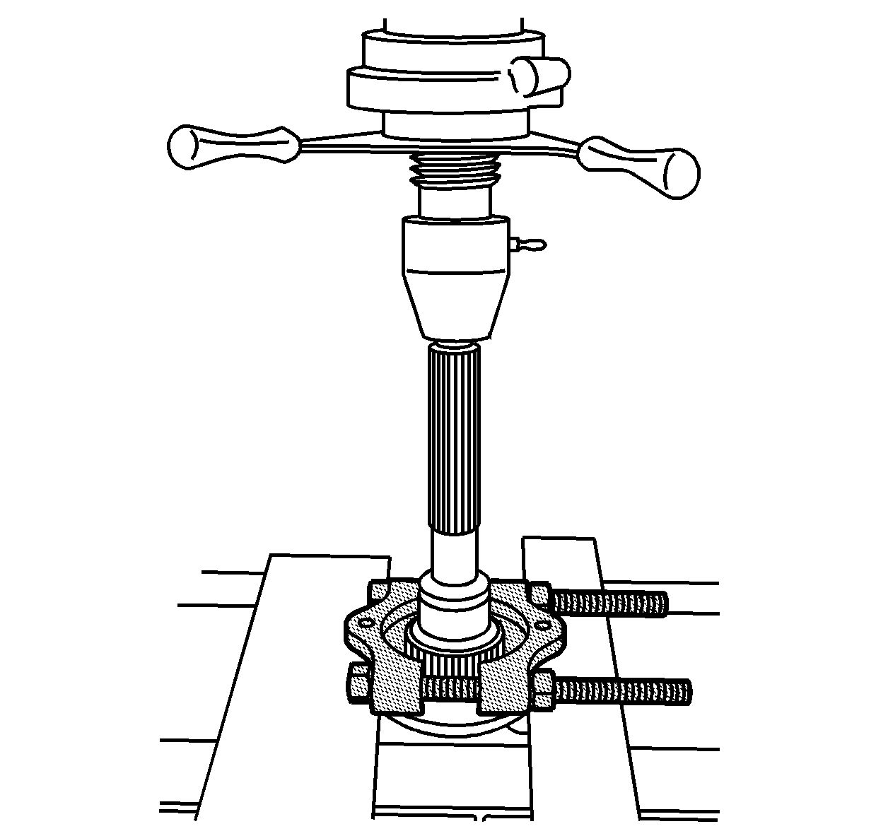
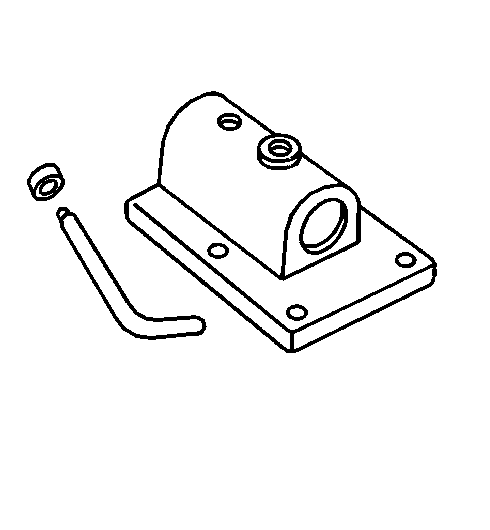
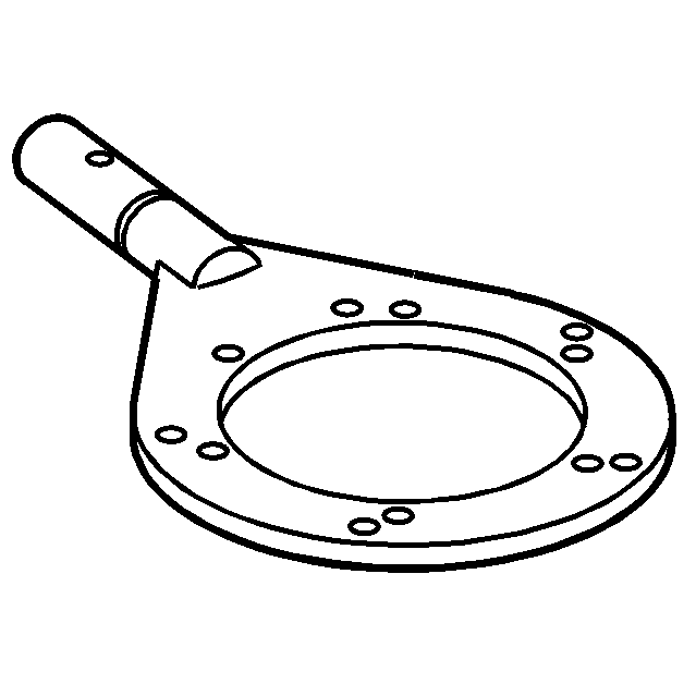
- Attach the
J 45759
to the
transfer case using the adapter studs. All of the transfer case disassembly procedures can be performed with the case mounted to the
J 45759
.
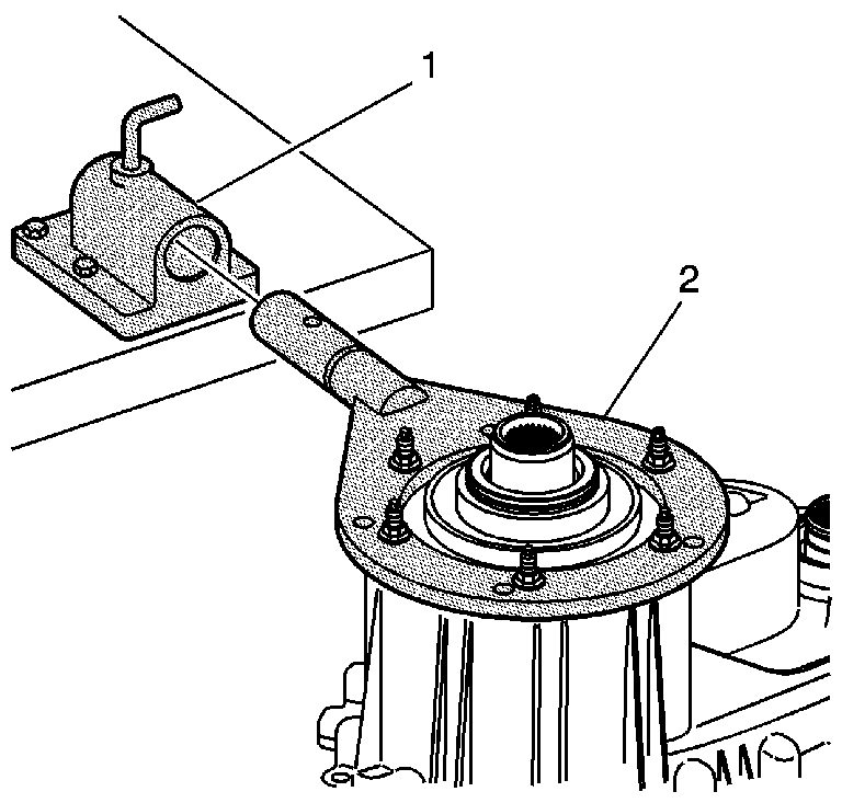
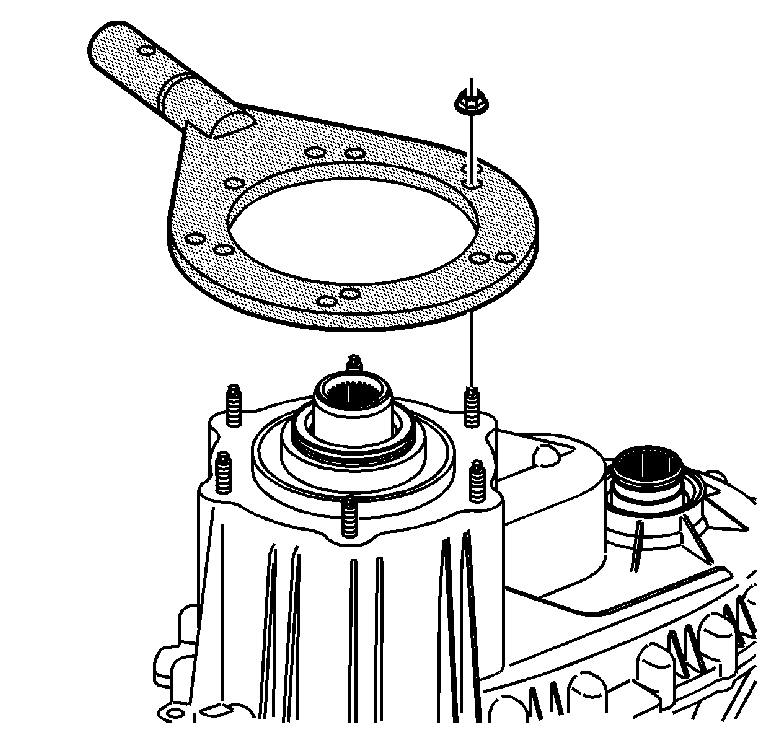
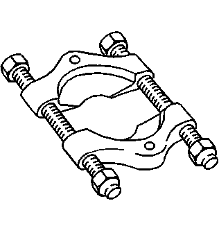
- Mount the
J 3289-20
(1) to a sturdy workbench.
- Install the
J 45759
(2) into
J 3289-20
(1) and secure with pivot pin.
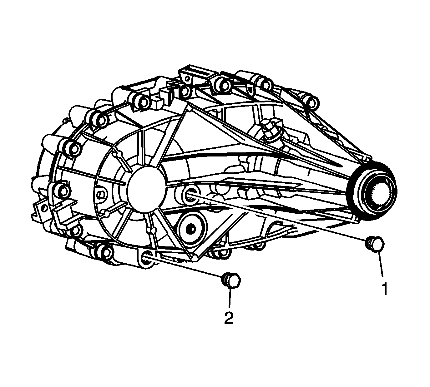
- Remove the drain plug (2) and the fill plug (1).
- Drain the fluid from the transfer case.
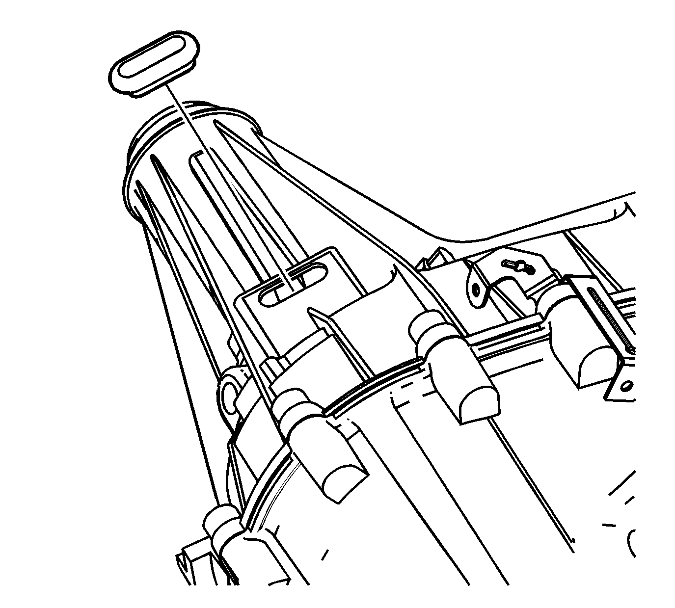
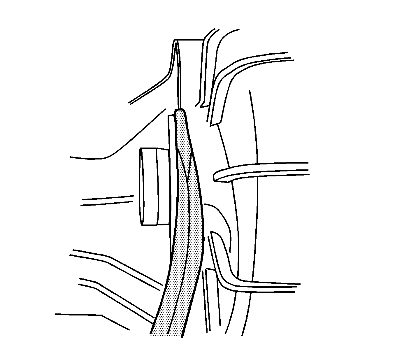
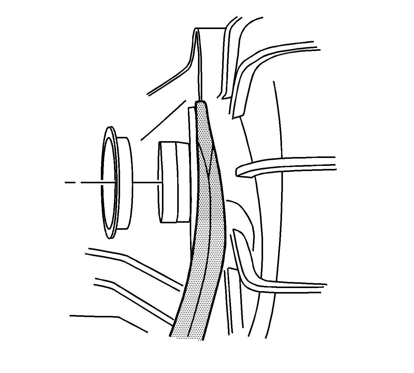
- Remove the access plug from the transfer case.
- Remove the transfer case vehicle speed sensor.
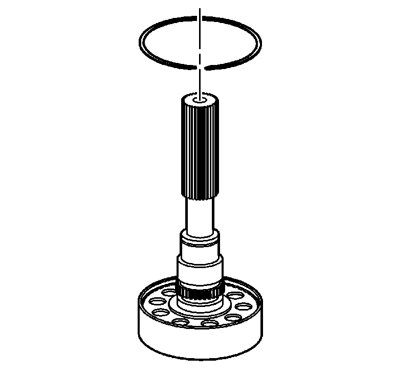
- Remove the plastic vent from the case; a NEW aluminum vent must be installed during assembly.
Notice: Refer to Transfer Case Seal Removal Notice in the Preface section.
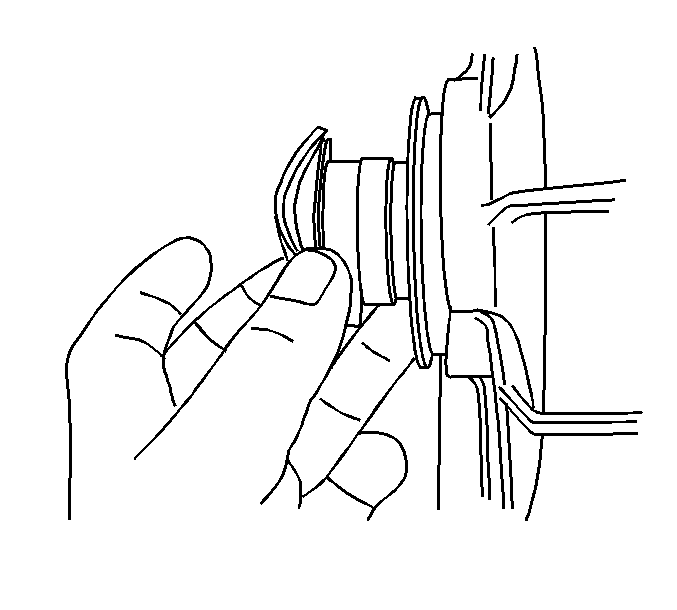
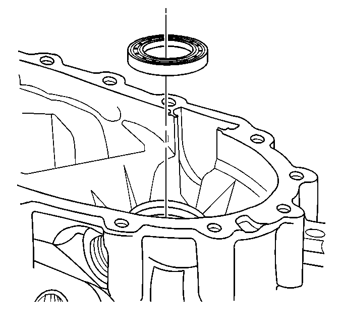
- Remove the input shaft seal.
- Remove the rear output shaft seal.
- Inspect the rear output shaft bushing for scoring or wear.
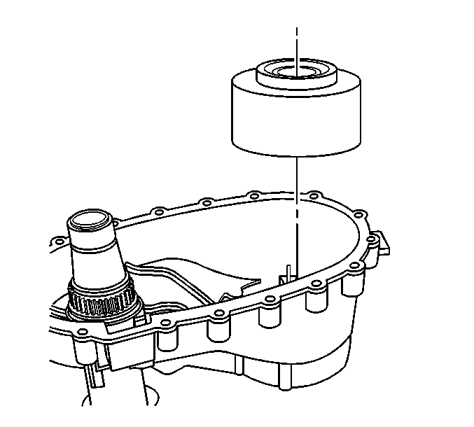
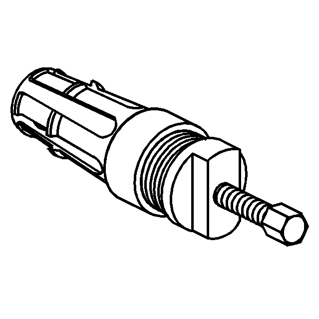
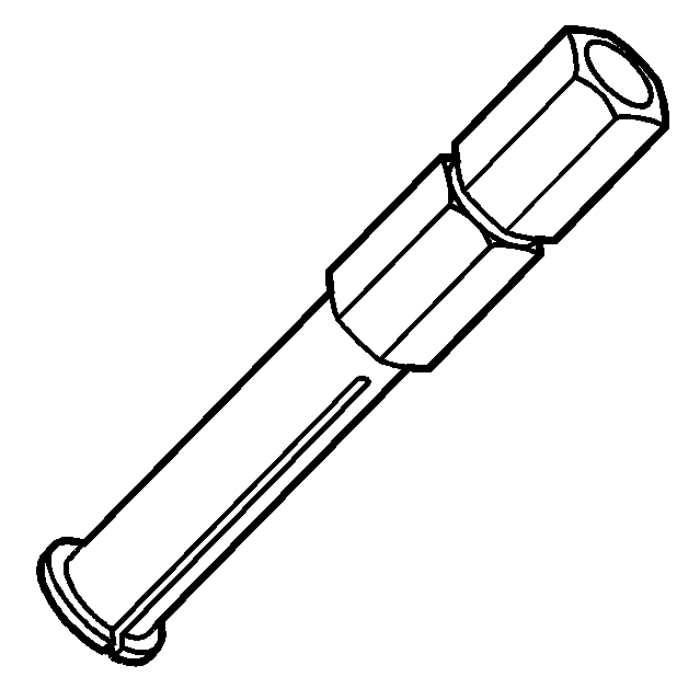
- Using the
J 45380
, remove the rear output shaft bushing.
| • | Install the finger section of the
J 45380
in front of the bushing. |
| • | Install the tube and forcing screw assembly to the finger section. Ensure the forcing screw is backed out. |
| • | Using a wrench on the forcing screw, remove the rear output shaft bushing. |
Notice: Refer to Transfer Case Seal Removal Notice in the Preface section.
Important: The front output shaft seal is a two piece internal style seal. The inner seal race is a force fit on the front output shaft.
- Remove the front output shaft seal by inserting a flat-tip screwdriver in the inner seal race.
- Pry the inner seal race forward.
- Using a small pry bar, move the inner seal race forward on the front output shaft.
- Remove the inner seal race from the front output shaft.
- Insert a flat-tip screwdriver or a small pry bar between the outer lip of the front output shaft seal and the transfer case.
- Remove the remaining part of the front output shaft seal from the transfer case.
Important:
| • | Mark the location of the brackets. |
| • | The magnesium transfer cases are using new style bolts that have a cup style washer. The cup washer is only available with the bolt. If the cup washer is not damaged, the bolt can be used again. |
- Remove the transfer case bolts, washers, and brackets.
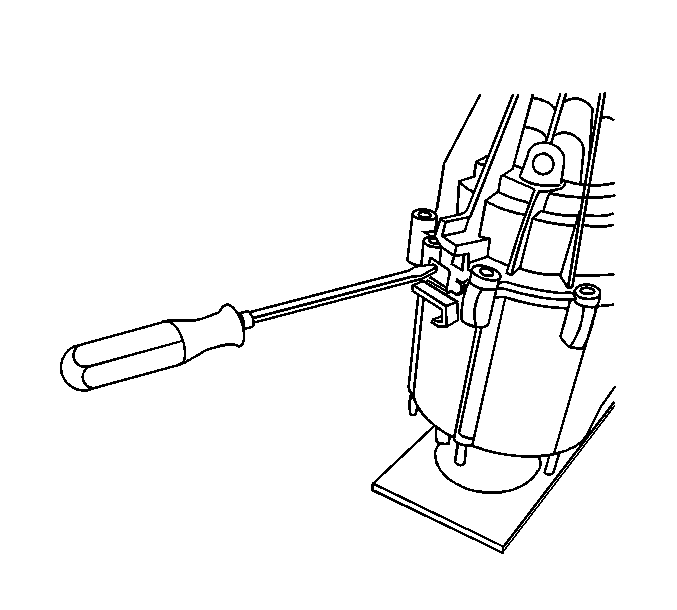
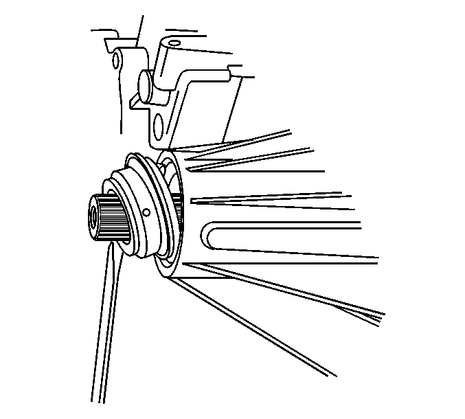
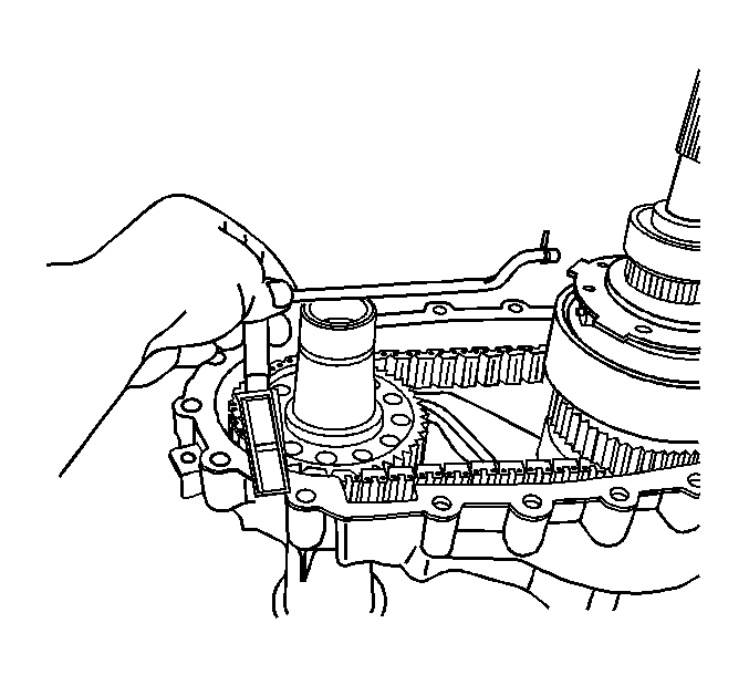
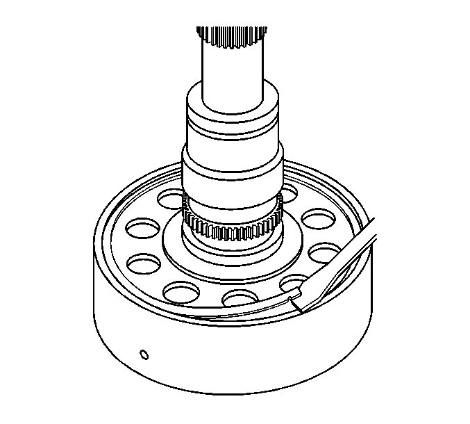
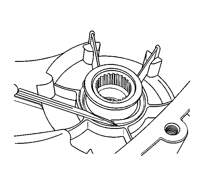
- Insert a flat-blade screwdriver in the slot on the left side of the transfer case.
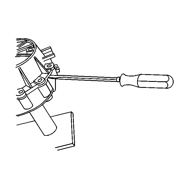
- Insert a flat-blade screwdriver in the slot on the right side if the transfer case.
- With equal pressure, press down on the screwdrivers.
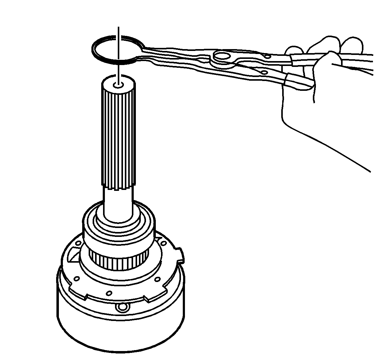
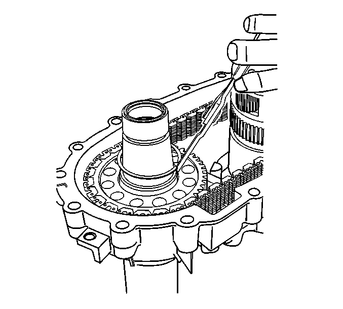
- Insert a pair of snap ring pliers into the slot.
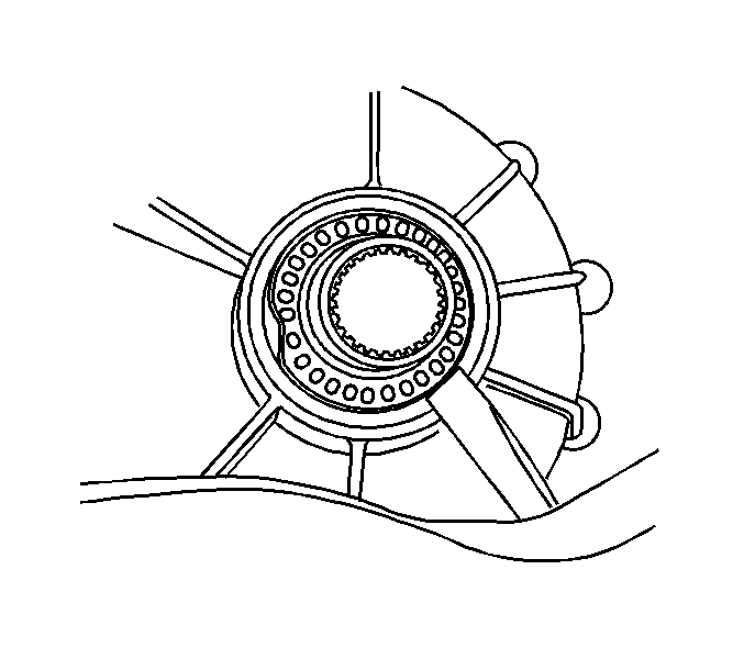
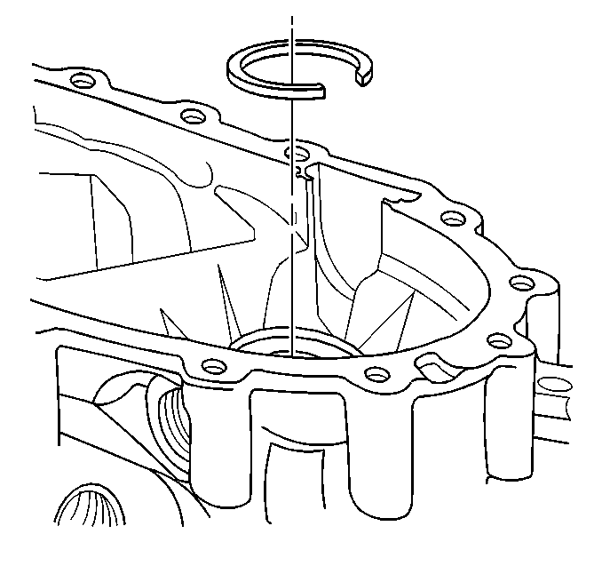
- Using the snap ring pliers, open the outer rear output shaft bearing retaining ring.
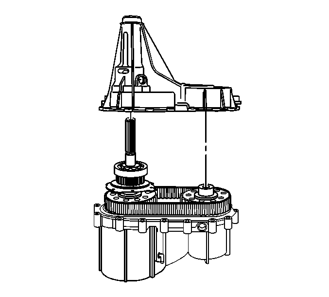
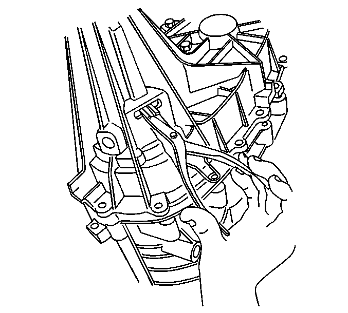
- Remove the rear case half from the front case half.
- Remove the oil pump screen assembly.
- Remove the rear output shaft assembly. Hold the planetary carrier in place to prevent removing it with the rear output shaft.
- Remove the rear output shaft bearing retaining ring.
- Using the flat side of the
J 22912-B
and a press, remove the rear output shaft
bearing.
Important: Move the oil pump retaining ring down and away from the tone wheel. This ensures that the
J 22912-B
does not get caught on the retaining ring.
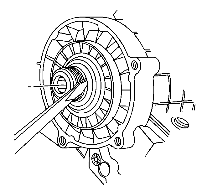
- Using the
J 22912-B
and a press, remove the speed reluctor wheel.
- Discard the speed reluctor wheel after removal.
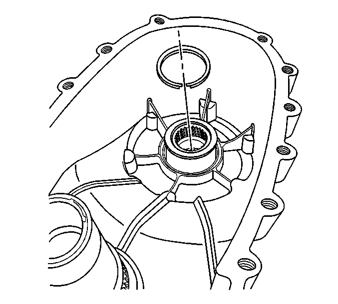
- Remove the oil pump retaining ring.
- Remove the oil pump assembly.
- Using a flat-blade screwdriver, unseat the annulus retaining ring.
- Remove the annulus gear retaining ring.
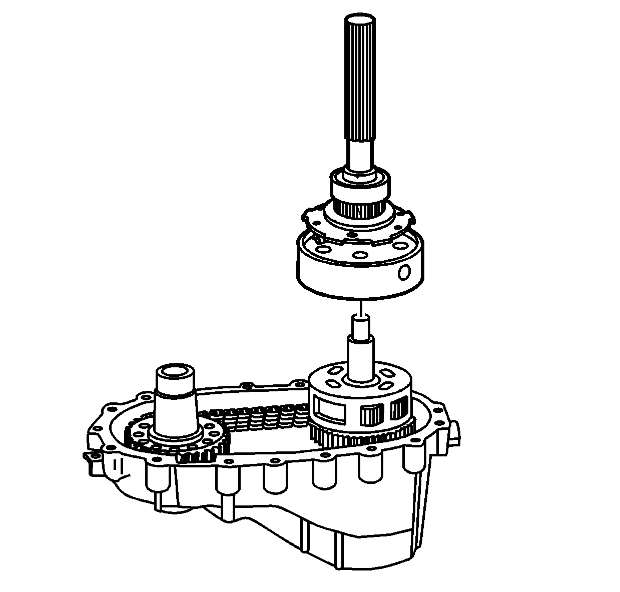
- Remove the rear output shaft.
- Inspect the mainshaft rear bushing in the rear output shaft for being faulty.
Refer to
Transfer Case Cleaning and Inspection
.
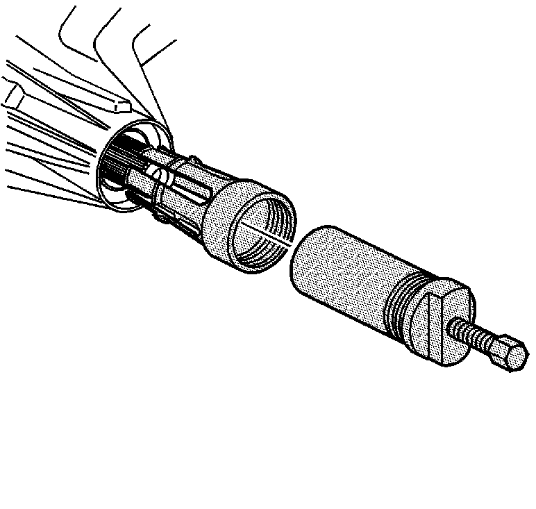
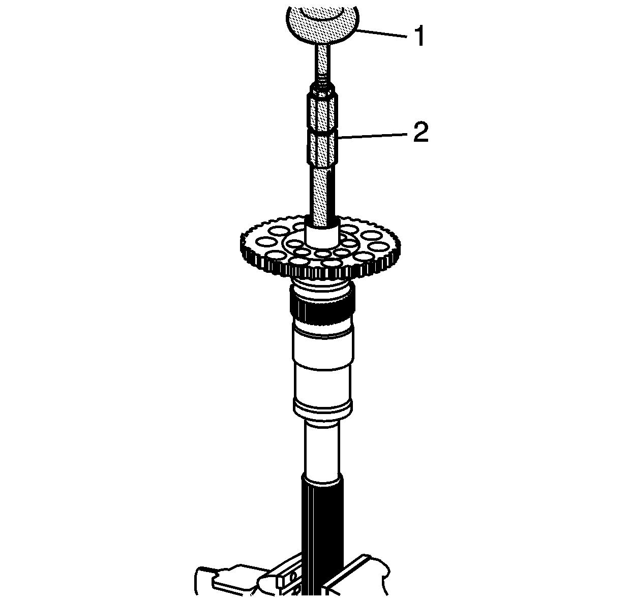
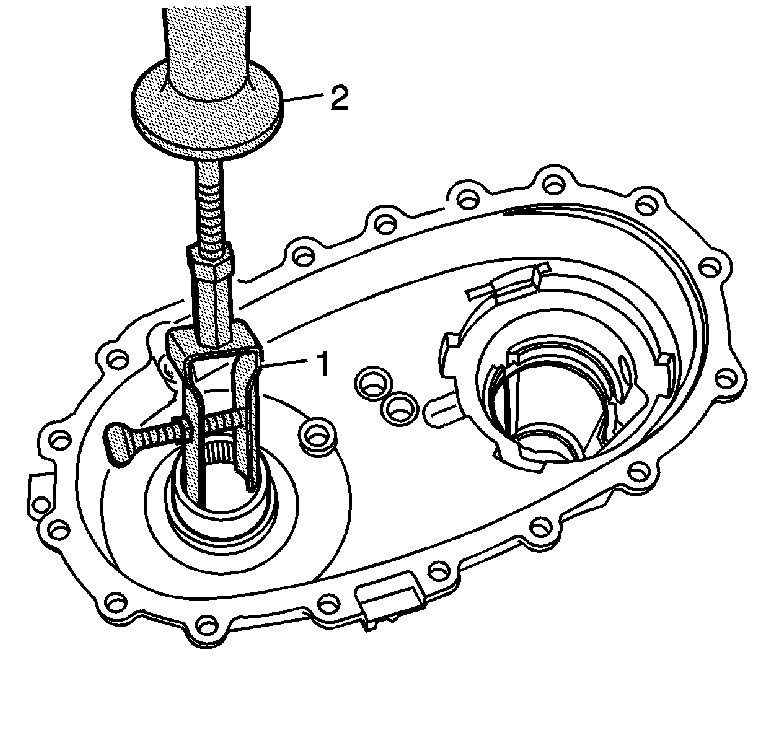
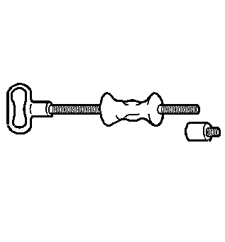
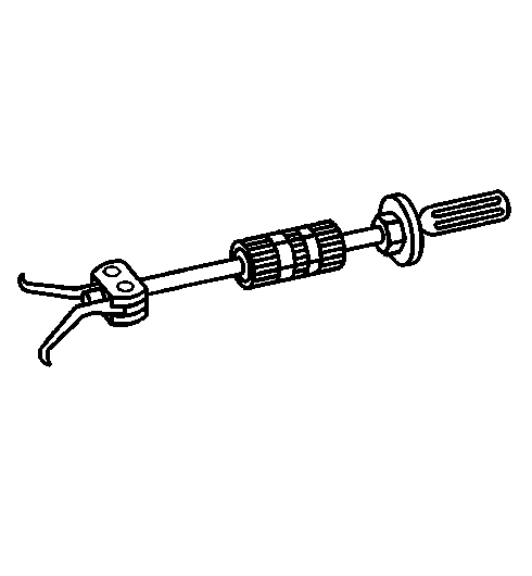
- Using the
J 2619-01
(1) and the
J 45548
(2), remove the mainshaft rear bushing.
- Remove the planetary carrier assembly. Tap on the end of the mainshaft with a soft-face hammer while lifting off the planetary carrier. A spring
style retaining ring holds the planetary carrier to the mainshaft.
- Remove the planetary carrier assembly thrust washer.
- Remove the sun gear.
- Remove the carrier retaining ring.
- Remove the mainshaft.
- Remove the planetary carrier sun gear bearing.
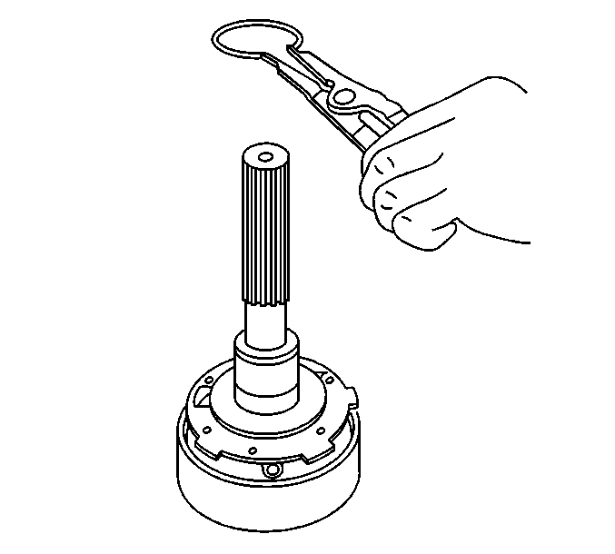
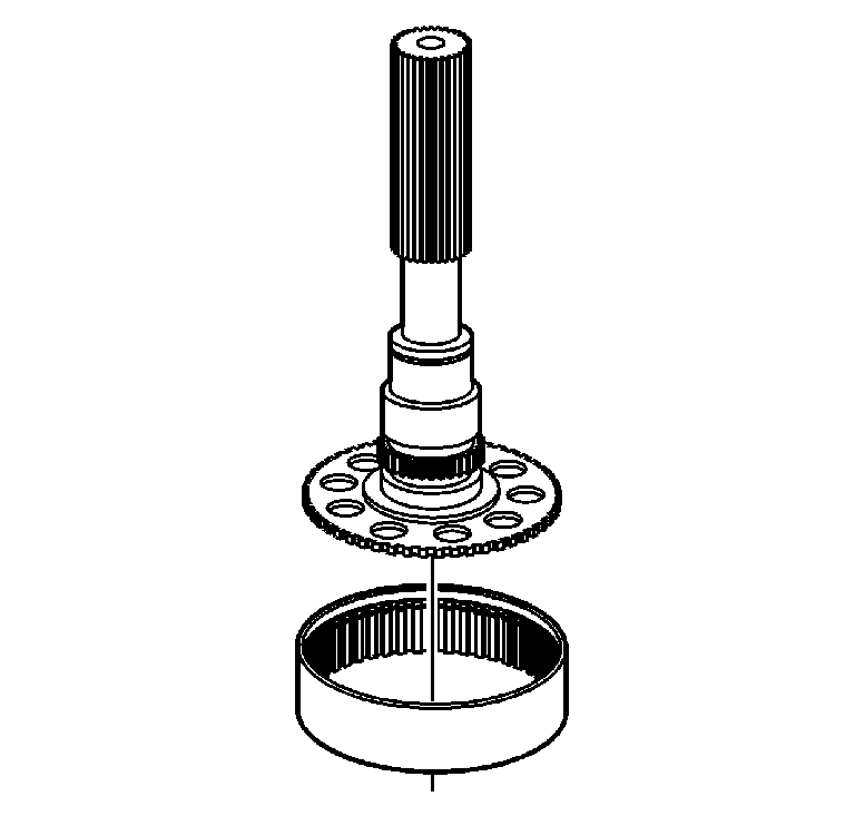
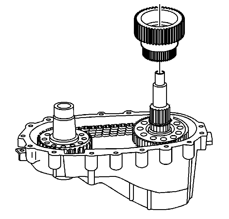
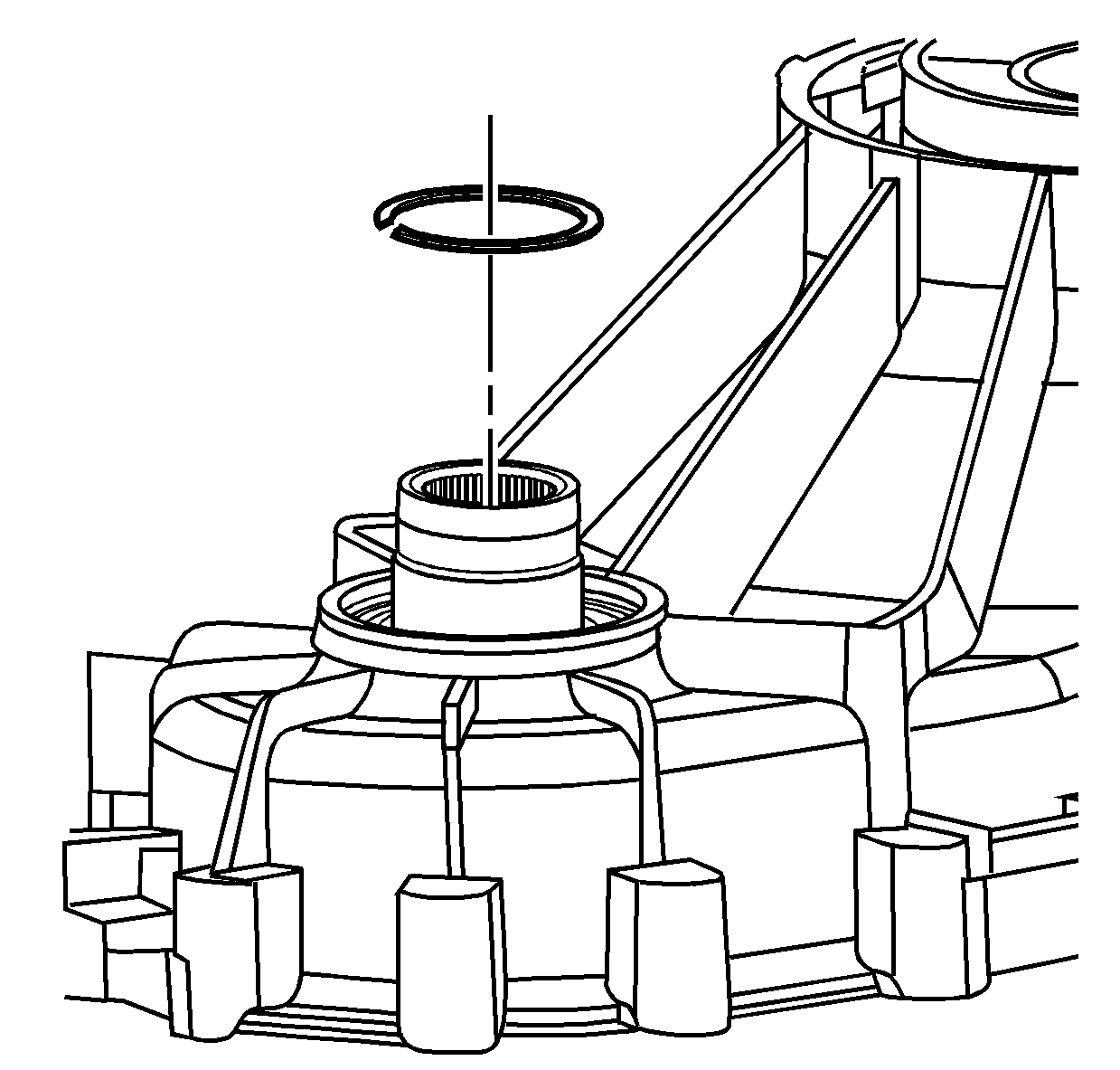
- Remove the driven sprocket retaining ring.
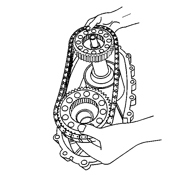
- Remove the drive chain assembly.
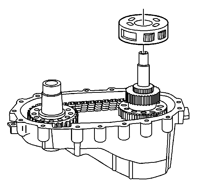
- Remove the viscous coupling.
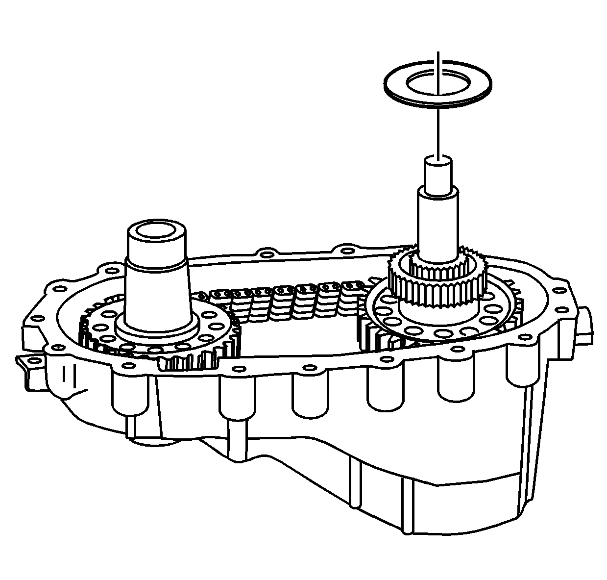
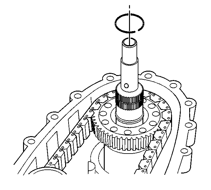
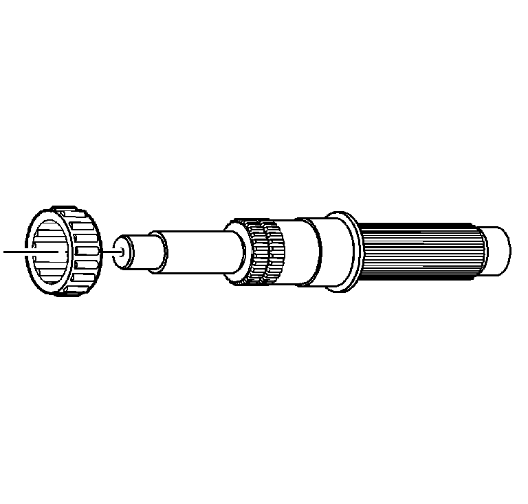
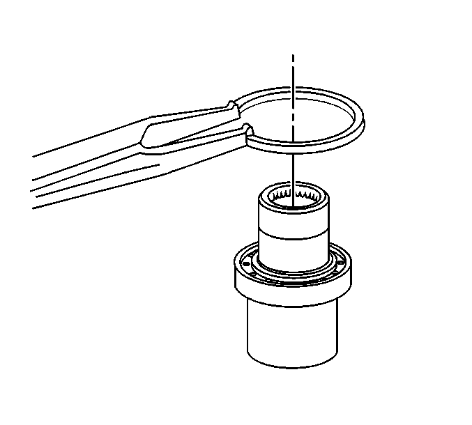
- Using a flat-blade screwdriver, remove the input gear bearing retaining ring from the groove.
- Remove the input gear bearing retaining ring.
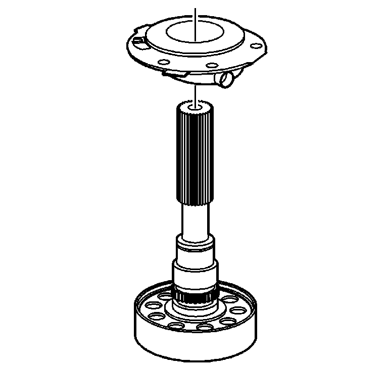
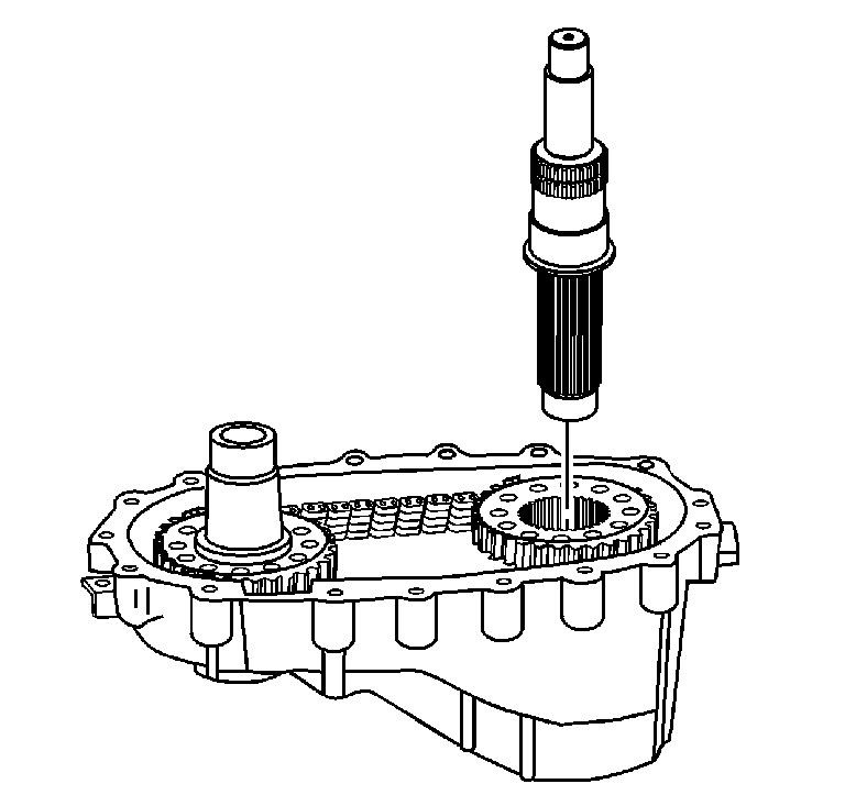
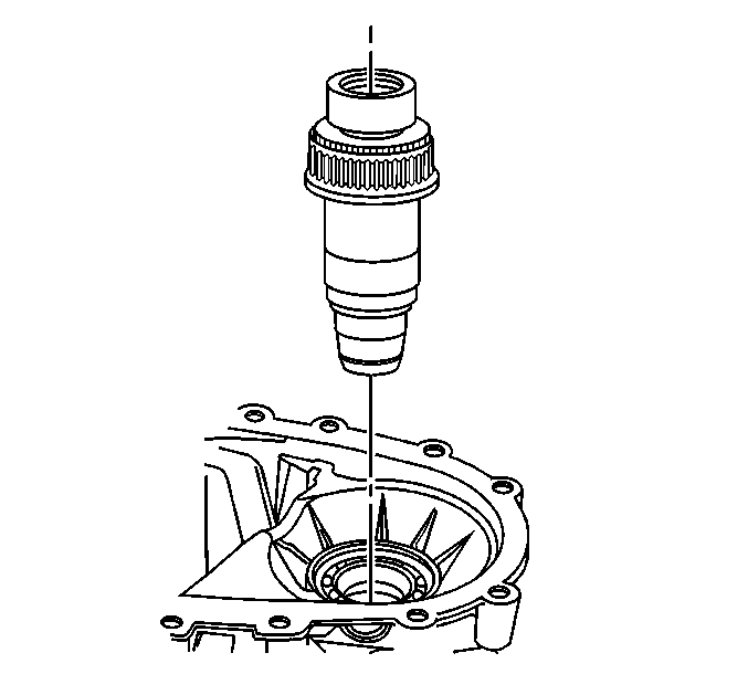
- Remove the input gear assembly.
- Remove the input gear bearing retaining ring.
- Using a press, remove the input bearing.
- Remove the front output shaft bearing
retaining ring.
- Remove the front output shaft assembly.
- Remove the front output shaft bearing retainer ring.
- Remove the front output shaft bearing.
- Inspect the front output shaft rear bearing. Refer to
Transfer Case Cleaning and Inspection
.
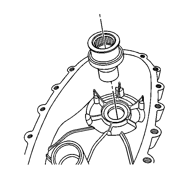
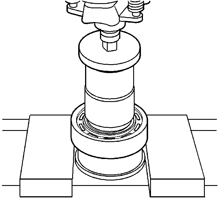
- Using the
J 23907
(2) and the
J 26941
(1), remove the front output shaft bearing from the rear case.
