For 1990-2009 cars only
Inspection Procedure
Prior to replacement inspect the following:
| • | Oil leaks on the shaft or around the schrader value |
| • | Rod guide to shaft end should be 2.75 in ± 0.15 in (7.0 cm ± 4.0 mm) |
Pry up on the alignment arm and release the arm should smoothly extend without binding.
Removal Procedure
- Raise the vehicle. Refer to Lifting and Jacking the Vehicle in General Information in 2005 C/K Truck Service Manual.
- Remove the tire and wheel. Refer to Tire and Wheel Removal and Installation in Tires and Wheels in 2005 C/K Truck Service Manual.
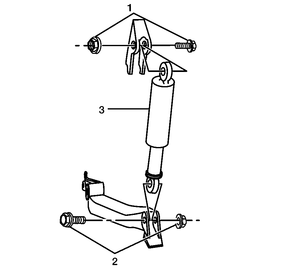
- Remove the lower shock nut and bolt (2).
- Remove the upper shock nut and bolt (1).
- Remove the jounce shock (3) from the vehicle.
Caution: Refer to Vehicle Lifting Caution in the Preface section.

Important: Do not discharge the internal pressure of the jounce shock. The loss of oil during discharge may affect the performance setting.
Installation Procedure
- Install the jounce shock (3) onto the vehicle. Ensure that the pressure fitting is facing the outside of the vehicle.
- Install the upper nut and bolt (1).
- Install lower nut and bolt (2).
- Install the tire and wheel. Refer to Tire and Wheel Removal and Installation in Tires and Wheels in 2005 C/K Truck Service Manual.
- Lower the vehicle. Refer to Lifting and Jacking the Vehicle in General Information in 2005 C/K Truck Service Manual.

Notice: Refer to Fastener Notice in the Preface section.
Tighten
Tighten bolt to 125 N·m (92 lb ft).
Tighten
Tighten bolt to 125 N·m (92 lb ft).
