For 1990-2009 cars only
Removal Procedure
- Remove the air intake pipe. Refer to Air Intake Pipe Replacement .
- Disconnect the air conditioning (A/C) compressor clutch electrical connector.
- Disconnect the A/C cut out switch electrical connector.
- Remove the drive belt. Refer to Drive Belt Replacement in Engine Mechanical - 6.6L.
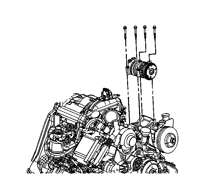
- Remove the A/C compressor bolts.
- Move the A/C compressor with the hoses attached to the right side of the engine compartment.
- Remove the water outlet tube. Refer to Water Outlet Tube Replacement in Engine Cooling.
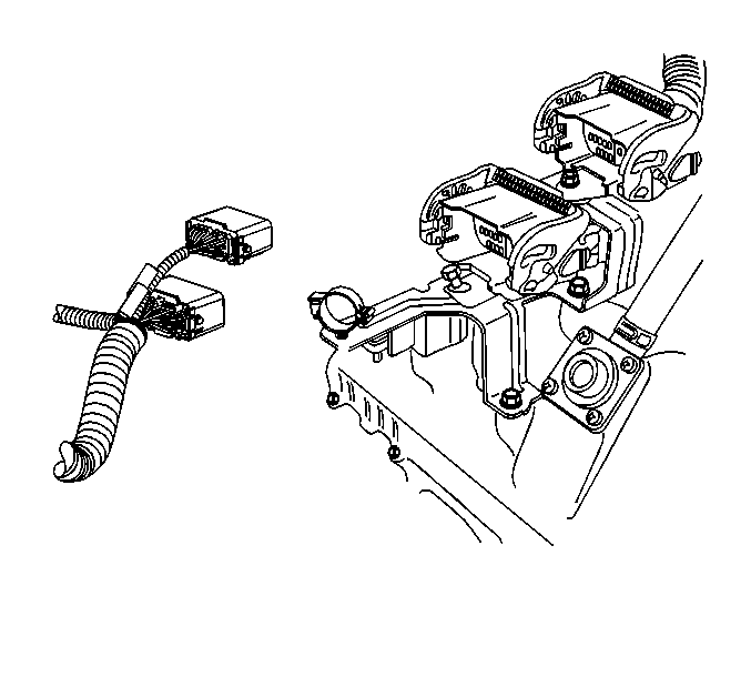
- Disconnect both main harness electrical connectors.
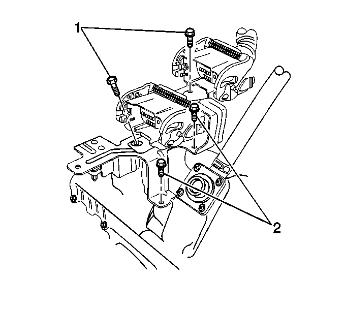
- Remove both main harness electrical connector to bracket bolts (1).
- Remove the main harnesses from the bracket.
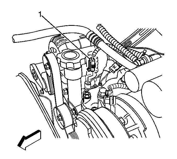
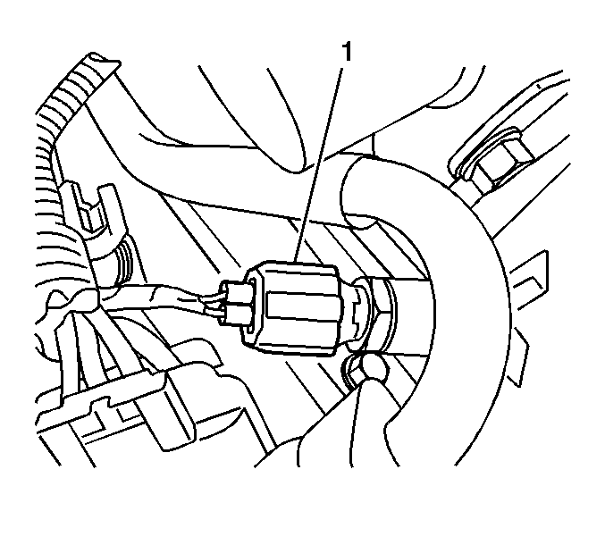
- Disconnect the engine coolant temperature (ECT) sensor electrical connector (1).
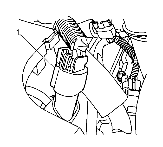
- Disconnect the barometric pressure (BARO) sensor electrical connector (1)
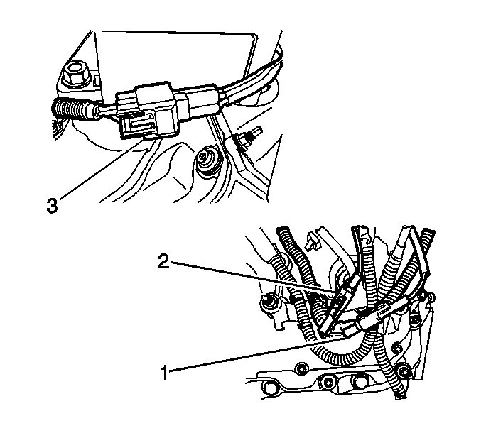
- Disconnect the glow plug relay electrical connectors (1, 2, 3).
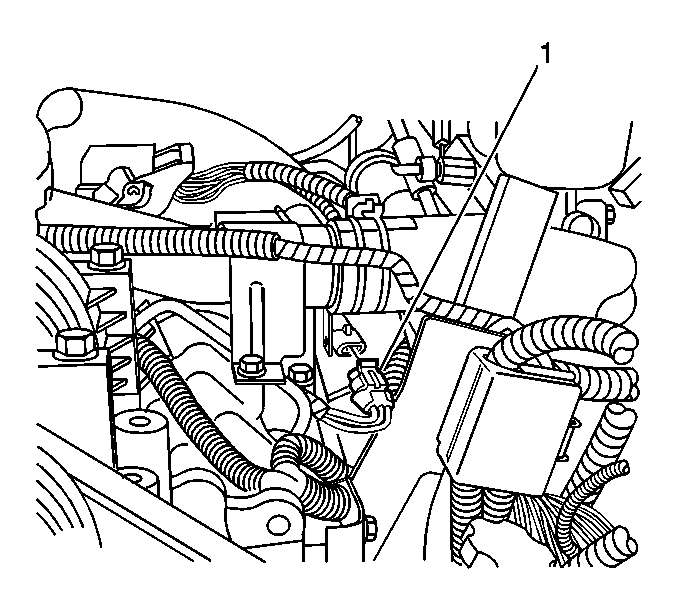
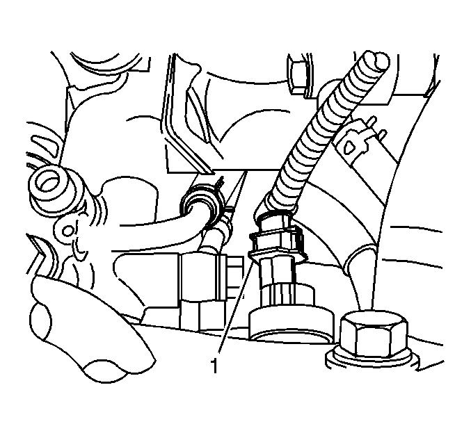
- Disconnect the fuel rail temperature sensor electrical connector (1).
- Disconnect the left front fuel injector electrical connector (1).
- Disconnect the left rear fuel injector electrical connector (1).
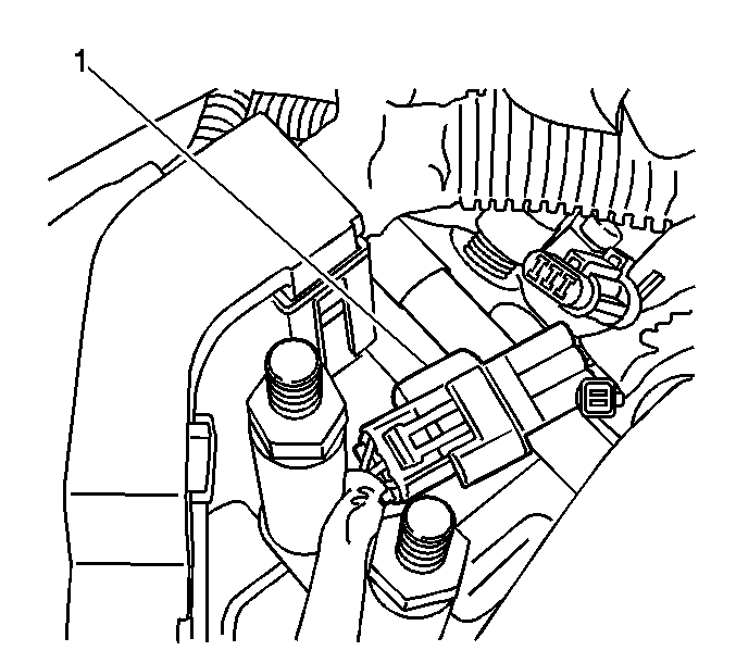
- Disconnect the fuel pressure regulator electrical connector (1).
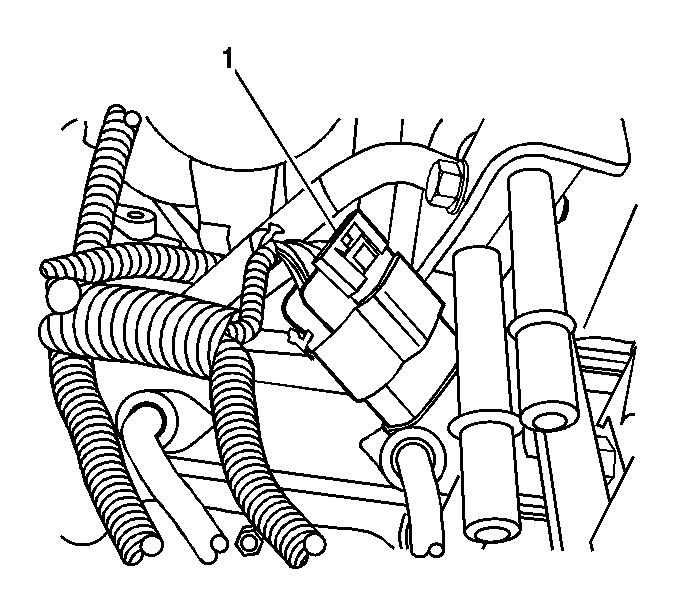
- Disconnect the oil level sensor harness electrical connector (1).
- Remove the positive crankcase ventilation (PCV) hose from both valve covers.
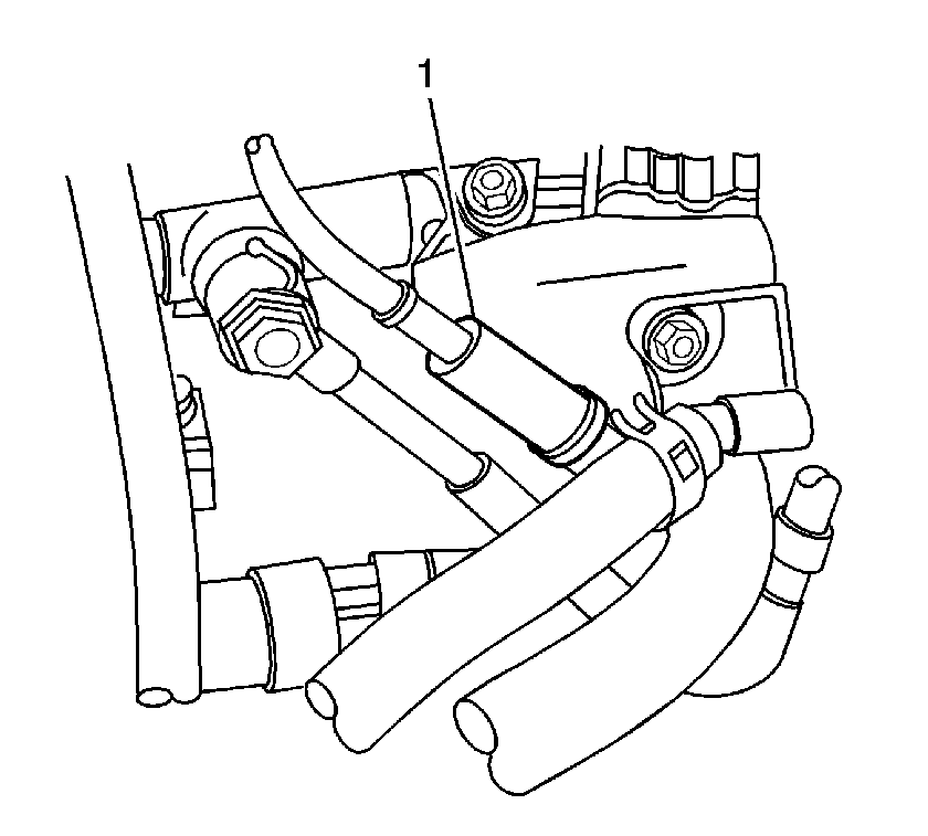
- Reposition the injection pump inlet clamp.
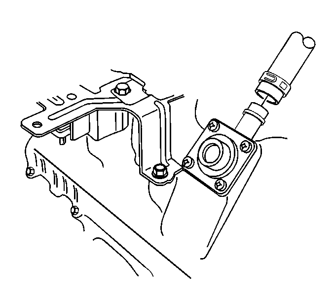
- Remove the injection pump inlet hose from the fuel feed distribution (leak-off) block. Reposition the hose.
- Clean the fuel pressure regulator and high pressure injection pump thoroughly with solvent, such as GM P/N 12377981 (Canadian P/N 10953463) or equivalent.
- Using compressed air, thoroughly blow dry the regulator and pump.
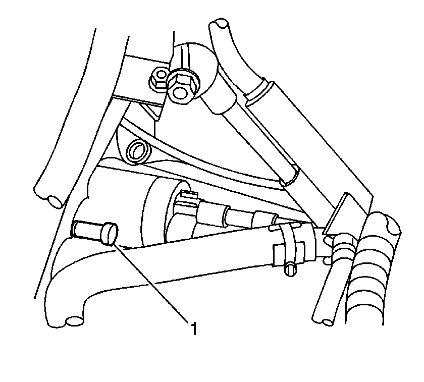
- Remove the 3 fuel pressure regulator screws (1) using a T25 TORX®.
- Remove the fuel pressure regulator (1).
- If dirt or debris is found in the bore or seating surfaces of the fuel injection pump, perform the following:
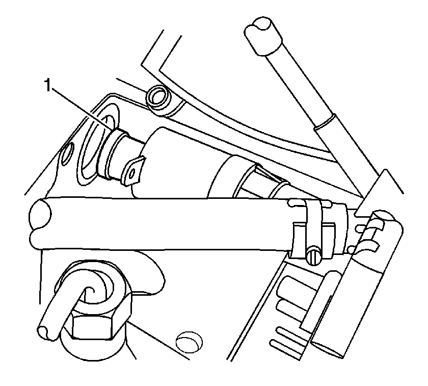
| • | Place a clean rag over the bore on order to collect the excess fuel. |
| • | Bump the engine over in order to flush any debris out of the regulator bore. |
Installation Procedure
Important: If the pressure regulator is being re-used, check the O-rings for damage. If the O-rings are damaged, install NEW O-rings.
- Lubricate and install NEW O-rings onto the regulator. Lubricate the O-rings with clean, NEW engine oil.
- Install the fuel pressure regulator (1).
- Install the 3 fuel pressure regulator screws (1) using a T25 TORX®.
- Install the injection pump inlet hose to the fuel feed distribution (leak) block.
- Position the injection pump inlet clamp.
- Install the PCV hose to both valve covers.
- Connect the oil level sensor harness electrical connector (1).
- Connect the fuel pressure regulator electrical connector (1).
- Connect the left rear fuel injector electrical connector (1).
- Connect the left front fuel injector electrical connector (1).
- Connect the fuel rail temperature sensor electrical connector (1).
- Connect the glow plug relay electrical connectors (1, 2, 3).
- Connect the BARO sensor electrical connector (1)
- Connect the ECT sensor electrical connector (1).
- Install the main harnesses to the bracket.
- Install both main harness electrical connector to bracket bolts (1).
- Connect both main harness electrical connectors.
- Install the water outlet tube. Refer to Water Outlet Tube Replacement in Engine Cooling.
- Position the A/C compressor.
- Install the A/C compressor bolts.
- Install the drive belt. Refer to Drive Belt Replacement in Engine Mechanical - 6.6L.
- Connect the A/C cut out switch electrical connector.
- Connect the A/C compressor clutch electrical connector.
- Install the air intake pipe. Refer to Air Intake Pipe Replacement .

Important: If the regulator is installed at an angle the O-rings may be damaged, resulting in possible fuel leakage.
Notice: Refer to Fastener Notice in the Preface section.

Tighten
| • | Tighten the screws a first pass to 4 N·m (35 lb in). |
| • | Tighten the screws a final pass to 7 N·m (62 lb in). |


Tighten
Tighten the bolts to 21 N·m (15 lb ft).


Tighten
Tighten the bolts to 53 N·m (37 lb ft).
