For 1990-2009 cars only
Generator Control Module Replacement 5.3L Engine w/RPO HP2
Removal Procedure
- Disconnect the energy storage box (ESB). Refer to Hybrid Battery Service Disconnect/Connect .
- Remove the air cleaner assembly. Refer to Air Cleaner Assembly Replacement in Engine Controls - 4.8L, 5.3L, and 6.0L.
- Remove the surge tank. Refer to Radiator Surge Tank Replacement in Engine Cooling.
- Remove the starter/generator control module (SGCM) coolant tank. Refer to Generator Control Module Coolant Tank Replacement in Engine Cooling.
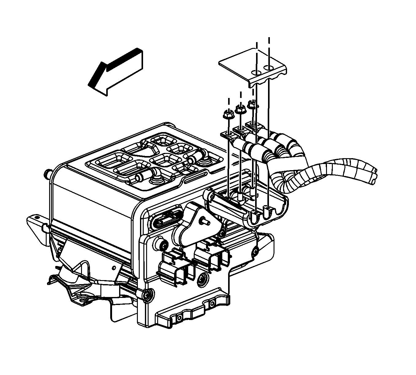
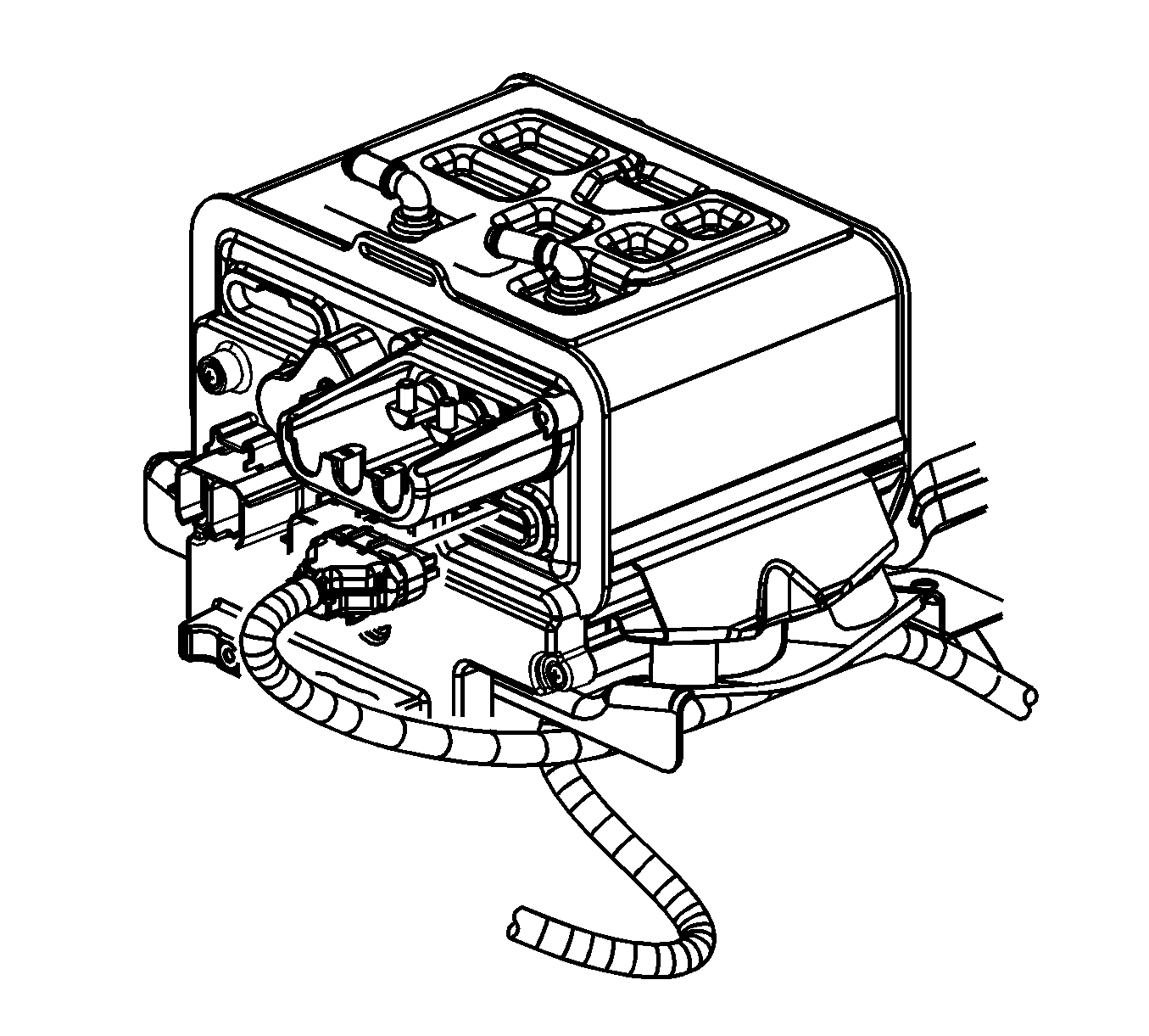
- Remove the SGCM cover bolts, and cover.
- Remove the 3-phase cable nuts to the SGCM.
- Remove the 3-phase cable from the SGCM.
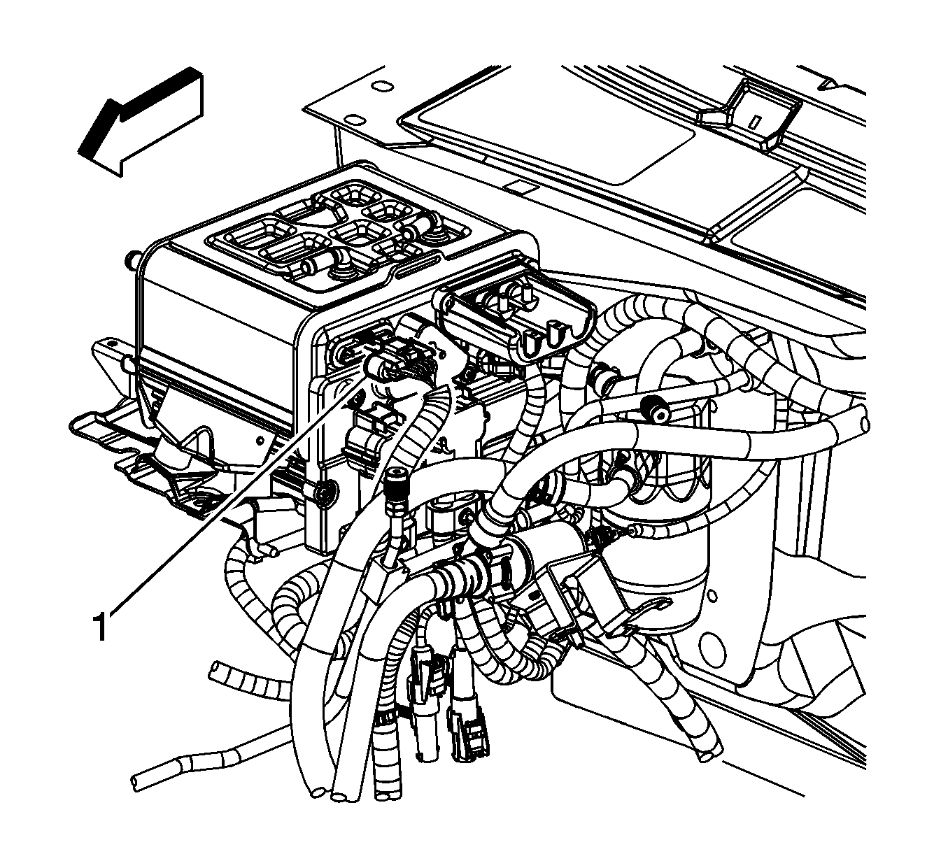
- Remove the connector position assurance (CPA) retainer on the engine harness electrical connector.
- Disconnect the engine harness electrical connector.
- Disconnect the accessory power receptacle electrical connector from the SGCM.
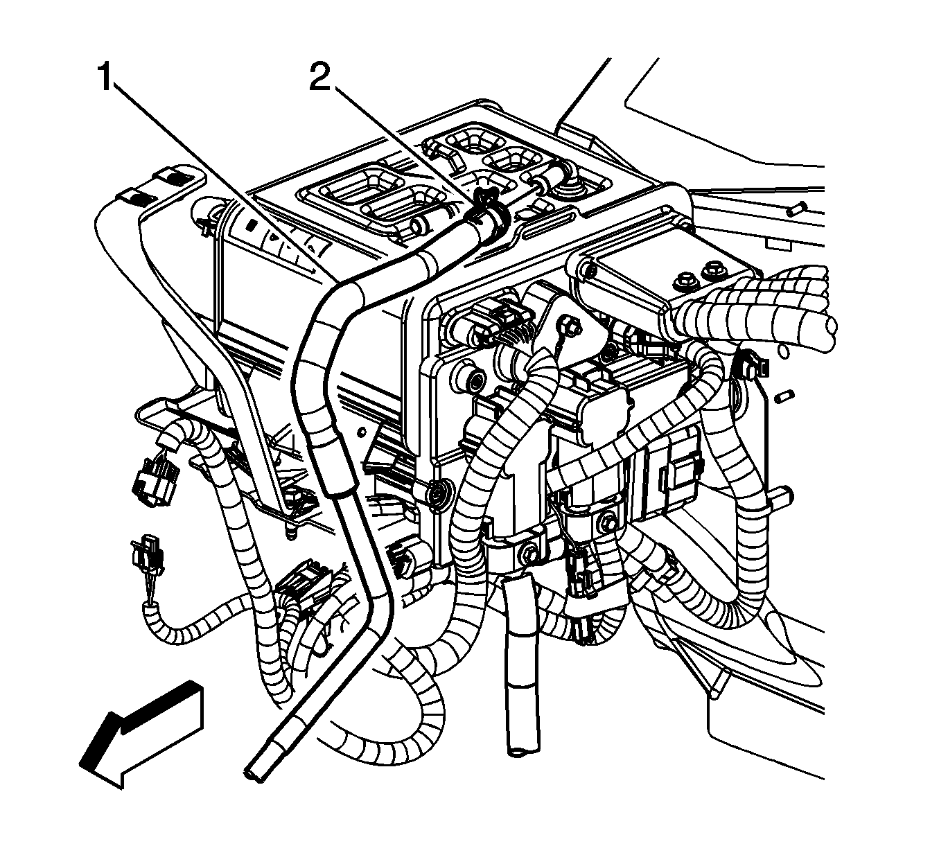
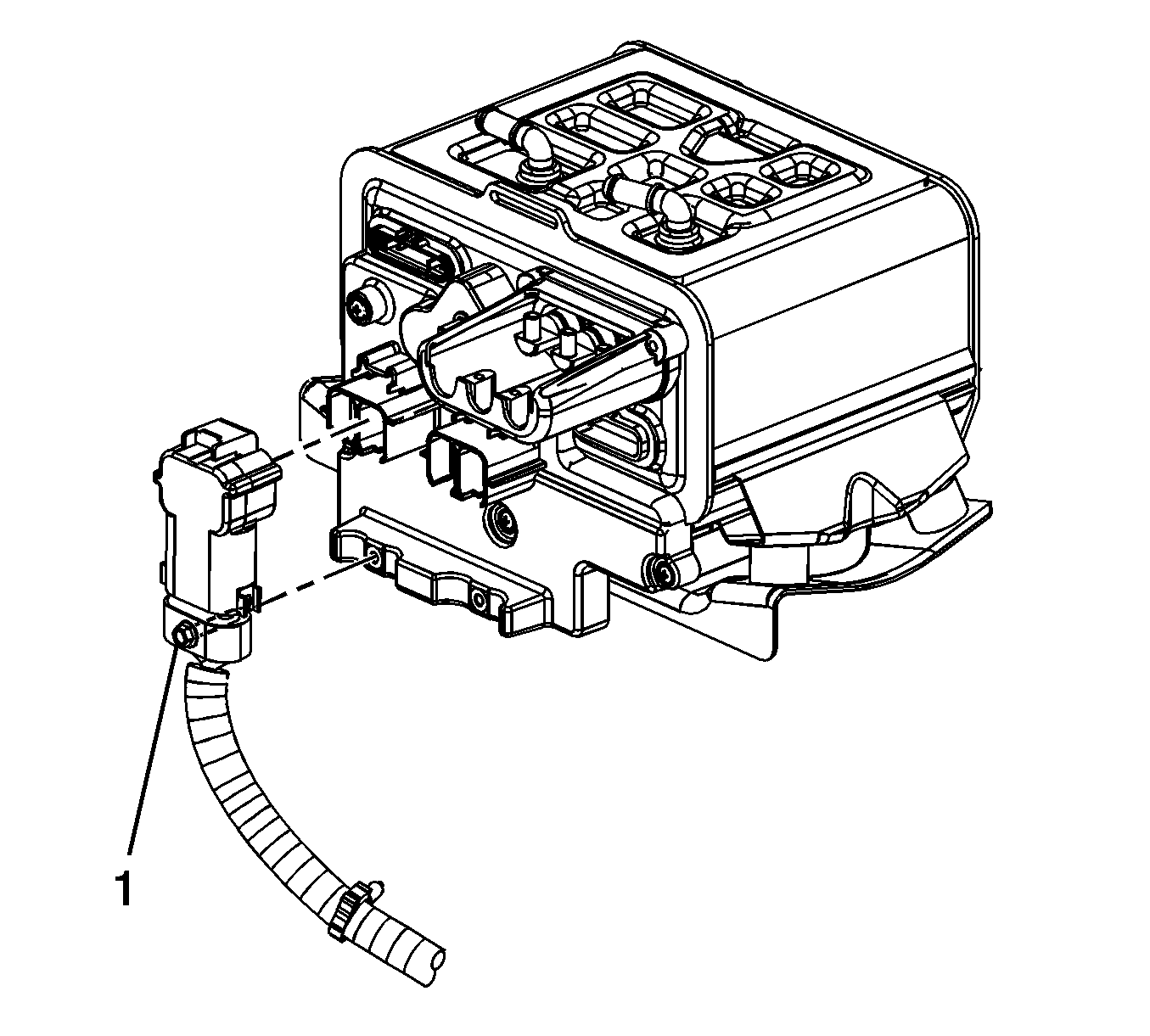
- Reposition the SGCM coolant outlet hose clamp (2).
- Remove the SGCM coolant outlet hose (1).
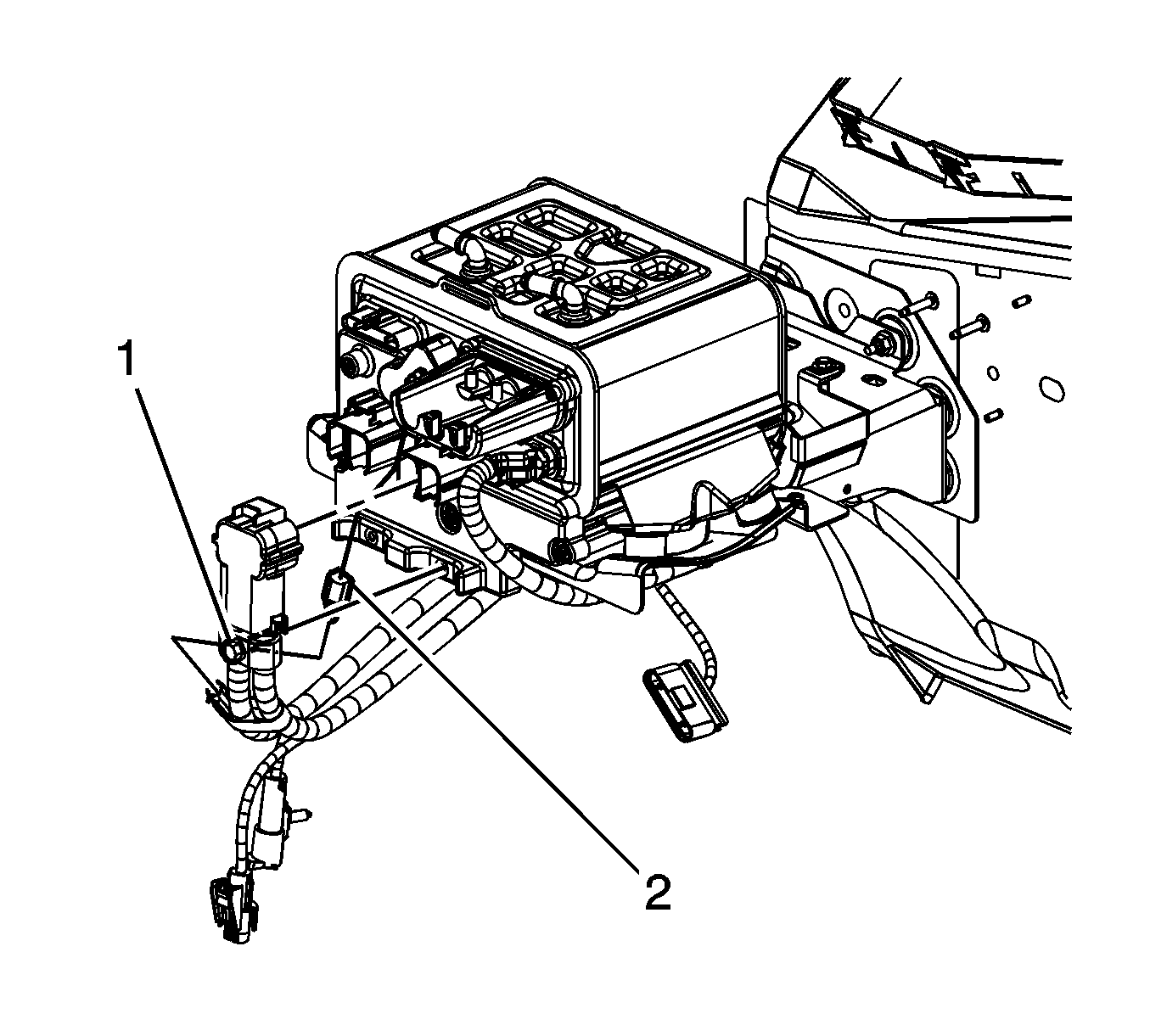
- Loosen the 14-volt positive/negative battery cable bolt (1).
- Remove the red connector position assurance (CPA) retainer.
- Disconnect the 14-volt positive/negative battery cable.
- Loosen the 42-volt positive/negative battery cable bolt (1).
- Remove the red CPA retainer.
- Disconnect the 42-volt positive/negative battery cable.
- Disconnect the 42-volt jumper ground wire connector (2).
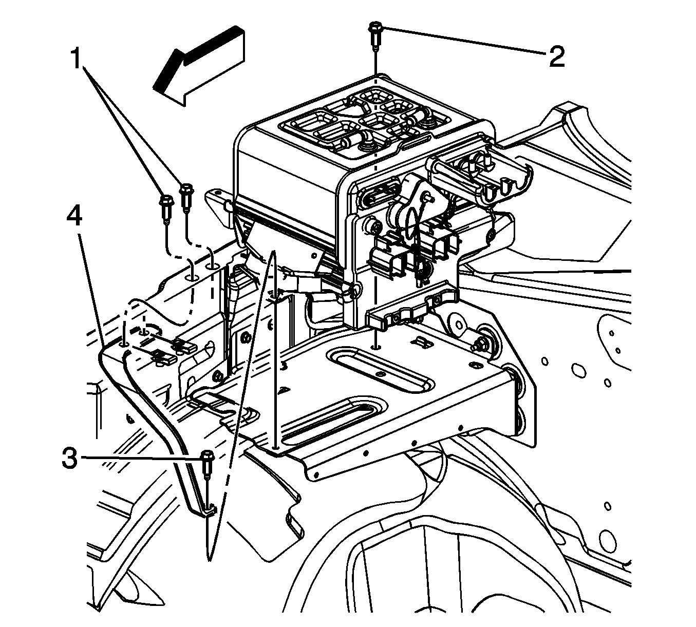
- Remove the SGCM rear bolt (2).
- Remove the SGCM front bolt (3).
- Remove the brace (4).
- Remove the SGCM.
Installation Procedure
- Install the SGCM.
- Install the brace (4).
- Install the SGCM front bolt (3).
- Install the SGCM rear bolt (2).
- Connect the 42-volt jumper ground wire connector (2).
- Connect the 42-volt positive/negative battery cable.
- Install the red CPA retainer.
- Tighten the 42-volt positive/negative battery cable bolt (1).
- Connect the 14-volt positive/negative battery cable.
- Install the red CPA retainer.
- Tighten the 14-volt positive/negative battery cable bolt (1).
- Install the SGCM coolant outlet hose (1).
- Position the SGCM coolant outlet hose clamp (2).
- Connect the accessory power receptacle electrical connector to the SGCM.
- Connect the engine harness electrical connector.
- Install the CPA retainer on the engine harness electrical connector.
- Install the 3-phase cable to the SGCM.
- Install the 3-phase cable nuts to the SGCM.
- Install the SGCM cover and bolts.
- Install the SGCM coolant tank. Refer to Generator Control Module Coolant Tank Replacement in Engine Cooling.
- Install the surge tank. Refer to Radiator Surge Tank Replacement in Engine Cooling.
- Install the air cleaner assembly. Refer to Air Cleaner Assembly Replacement in Engine Controls - 4.8L, 5.3L, and 6.0L.
- Connect the ESB. Refer to Hybrid Battery Service Disconnect/Connect .
- Program the SGCM. Refer to Service Programming System (SPS) in Programming and Setup.

Notice: Refer to Fastener Notice in the Preface section.
Tighten
Tighten the bolts to 20 N·m (15 lb ft).

Tighten
Tighten the bolt to 9 N·m (80 lb in).

Tighten
Tighten the bolt to 9 N·m (80 lb in).


Tighten
Tighten the nuts to 15 N·m (11 lb ft).
Tighten
Tighten the bolts to 9 N·m (80 lb in).
