Rear Disc Brake Backing Plate Replacement 15 Series w/o NYS
Caution: Refer to Brake Dust Caution in the Preface section.
Removal Procedure
- Release the park brake.
- Raise and support the vehicle. Refer to Lifting and Jacking the Vehicle in General Information.
- Remove the tire and wheel assembly. Refer to Tire and Wheel Removal and Installation in Tires and Wheels.
- Relieve the tension from the park brake cables by loosening the nut at the equalizer.
- Perform the following procedure to remove the cable from the backing plate:
- Remove the rotor. Refer to Rear Brake Rotor Replacement .
- Remove the axle shaft. Refer to Rear Axle Shaft Replacement in Rear Drive Axle.
- Remove the park brake shoe. Refer to Parking Brake Shoe Replacement .
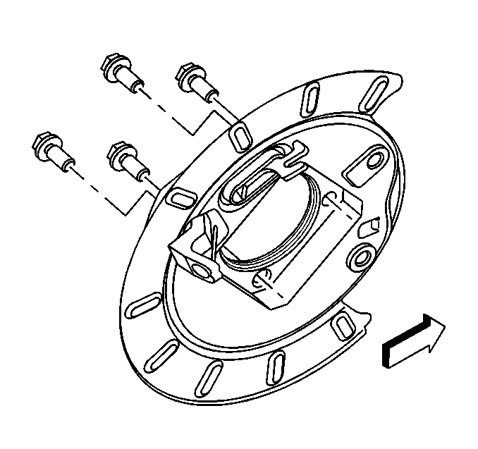
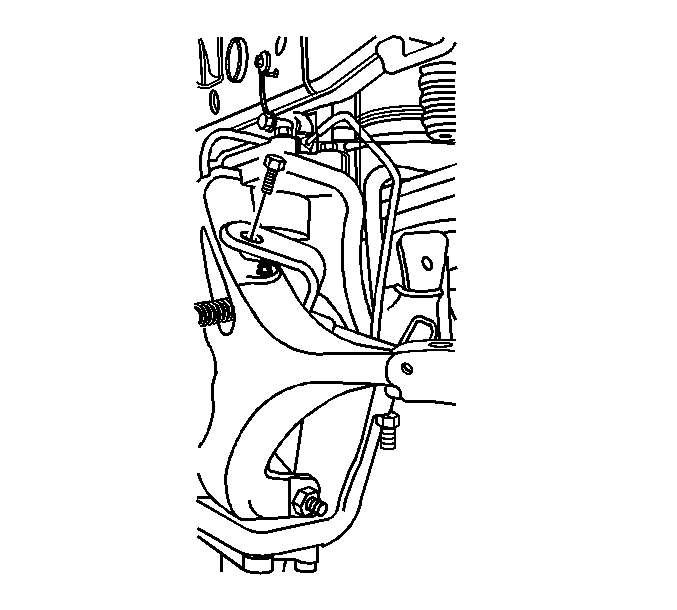
- Remove the backing plate bolts.
- Remove the backing plate from axle housing flange.
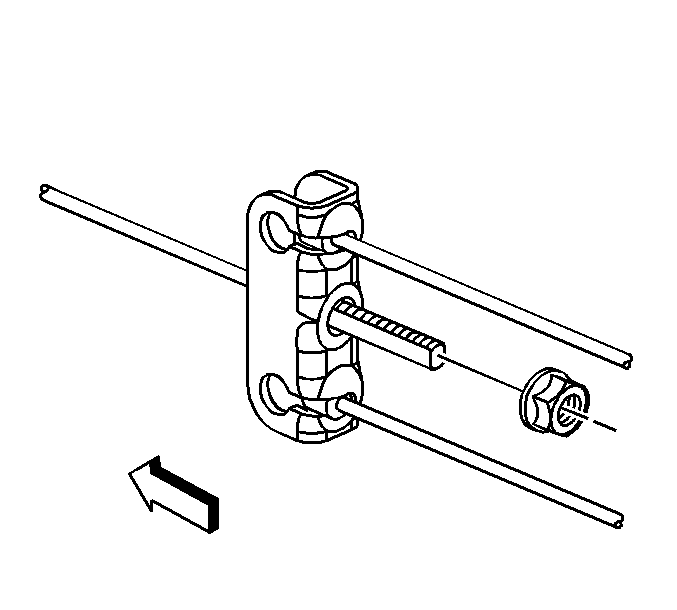
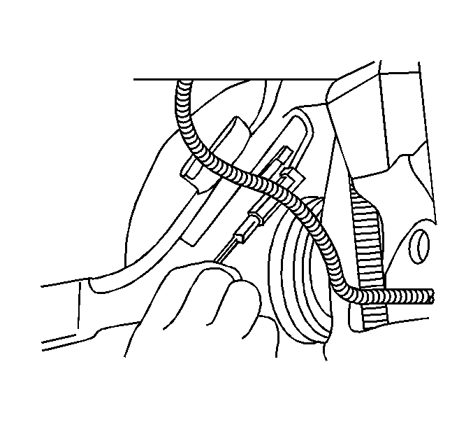
| 5.1. | Compress the spring by pushing towards the lever. |
| 5.2. | Depress the locking tabs. |
| 5.3. | Pull the cable housing out of the backing plate. |
| 5.4. | Remove the cable through the slot in the backing plate. |
Installation Procedure
- Install the backing plate to the axle housing flange.
- Perform the following procedure before installing the backing plate bolts (15 Series only).
- Install the backing plate bolts.
- Install the park brake shoe. Refer to Parking Brake Shoe Replacement .
- Install the axle shaft. Refer to Rear Axle Shaft Replacement in Rear Drive Axle.
- Adjust the park brake shoe. Refer to Park Brake Adjustment .
- Install the rotor. Refer to Rear Brake Rotor Replacement .
- Install the park brake cable to the lever.
- Perform the following procedure to install the cable to the backing plate:
- Tighten the nut to the intermediate cable at the equalizer.
- Install the tire and wheel assembly. Refer to Tire and Wheel Removal and Installation in Tires and Wheels.
- Remove the safety stands.
- Lower vehicle.
- Adjust park brake cable. Refer to Park Brake Adjustment .
| 2.1. | Remove all traces of the original adhesive patch. |
| 2.2. | Clean the threads of the bolt with brake parts cleaner or the equivalent and allow to dry. |
| 2.3. | Apply Threadlocker GM P/N 12345493 (Canadian P/N 10953488) to the threads of the bolt. |
Notice: Use the correct fastener in the correct location. Replacement fasteners must be the correct part number for that application. Fasteners requiring replacement or fasteners requiring the use of thread locking compound or sealant are identified in the service procedure. Do not use paints, lubricants, or corrosion inhibitors on fasteners or fastener joint surfaces unless specified. These coatings affect fastener torque and joint clamping force and may damage the fastener. Use the correct tightening sequence and specifications when installing fasteners in order to avoid damage to parts and systems.
Tighten
Tighten the backing plate bolts to 135 N·m (100 lb ft).
| 9.1. | Compress the spring by pushing towards the lever. |
| 9.2. | Route the cable through the slot in the backing plate. |
| 9.3. | Push the cable housing into the backing plate until the locking tabs snap into place. |
Notice: Use the correct fastener in the correct location. Replacement fasteners must be the correct part number for that application. Fasteners requiring replacement or fasteners requiring the use of thread locking compound or sealant are identified in the service procedure. Do not use paints, lubricants, or corrosion inhibitors on fasteners or fastener joint surfaces unless specified. These coatings affect fastener torque and joint clamping force and may damage the fastener. Use the correct tightening sequence and specifications when installing fasteners in order to avoid damage to parts and systems.
Tighten
Tighten the nut to 3.5 N·m (31 lb in).
Rear Disc Brake Backing Plate Replacement 15 Series W/NYS
Caution: Refer to Brake Dust Caution in the Preface section.
Removal Procedure
- Release the park brake.
- Raise and support the vehicle. Refer to Lifting and Jacking the Vehicle in General Information.
- Remove the tire and wheel assembly. Refer to Tire and Wheel Removal and Installation in Tires and Wheels.
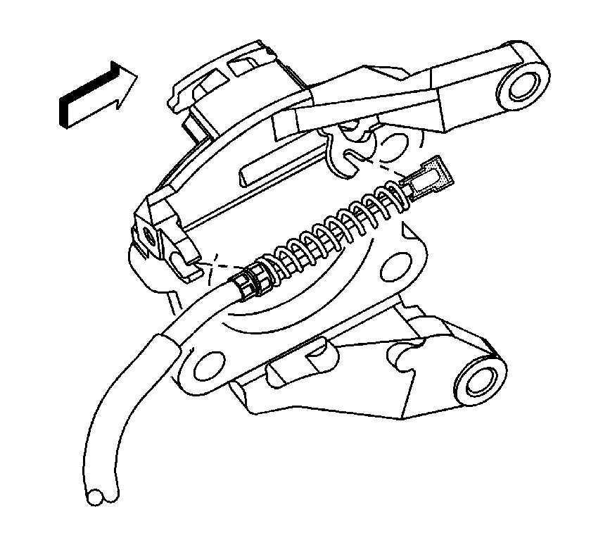
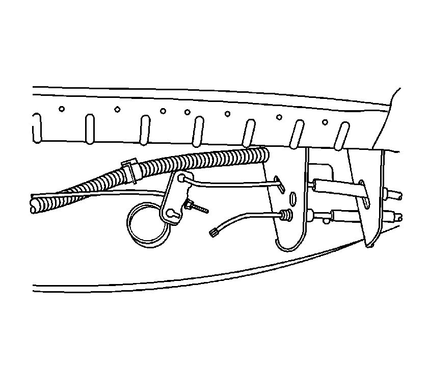
- Relieve the tension from the park brake cable by pulling down on the intermediate cable then release the cable from the equalizer bar.
- Remove the rear park brake bracket bolt.
- Remove the park brake cable from the park brake actuator lever.
- Remove the wheel bearing. Refer to Wheel Hub and Bearing Replacement in Rear Wheel Steering.
- Remove the park brake shoe.
- Remove the park brake actuator lever housing from the backing plate.
- Remove the backing plate.
Installation Procedure
- Install the park brake actuator lever housing to the backing plate.
- Install the park brake shoe.
- Install the wheel bearing and adjust the park brake shoe. Refer to Wheel Hub and Bearing Replacement in Rear Wheel Steering and Park Brake Adjustment in Park Brake.
- Install the park brake cable to the park brake actuator lever.
- Install the rear park brake bracket bolt.
- Install the park brake cable to the equalizer bar.
- Install the tire and wheel assembly. Refer to Tire and Wheel Removal and Installation in Tires and Wheels.
- Lower the vehicle.
Notice: Use the correct fastener in the correct location. Replacement fasteners must be the correct part number for that application. Fasteners requiring replacement or fasteners requiring the use of thread locking compound or sealant are identified in the service procedure. Do not use paints, lubricants, or corrosion inhibitors on fasteners or fastener joint surfaces unless specified. These coatings affect fastener torque and joint clamping force and may damage the fastener. Use the correct tightening sequence and specifications when installing fasteners in order to avoid damage to parts and systems.
Tighten
Tighten the bolt to 61 N·m (45 lb ft).
Rear Disc Brake Backing Plate Replacement 25/35 Series
Caution: Refer to Brake Dust Caution in the Preface section.
Removal Procedure
- Disable the park brake cable automatic adjuster. Refer to Parking Brake Cable Adjuster Disabling in Park Brake.
- Raise and support the vehicle. Refer to Lifting and Jacking the Vehicle in General Information.
- Remove the tire and wheel assembly. Refer to Tire and Wheel Removal and Installation in Tires and Wheels.
- Perform the following procedure to remove the cable (2) from the backing plate (4):
- Remove the park brake cable (2) from the lever (1).
- Remove the rotor. Refer to Rear Brake Rotor Replacement .
- Remove the axle shaft. Refer to Rear Axle Shaft Replacement in Rear Drive Axle.
- Remove the park brake shoe. Refer to Parking Brake Shoe Replacement .
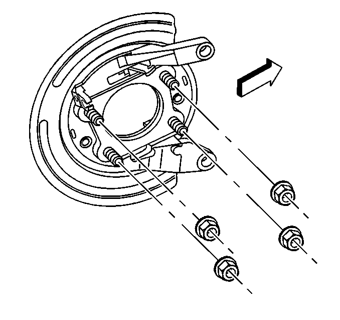
- Remove the backing plate nuts.
- Remove the backing plate from the axle housing flange.
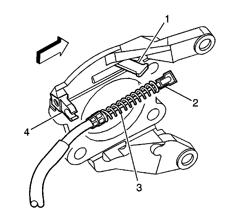
| 4.1. | Compress the spring (3) by pushing towards the lever (1). |
| 4.2. | Depress the locking tabs. |
| 4.3. | Pull the cable housing out of the backing plate (4). |
| 4.4. | Remove the cable (2) through the slot in the backing plate. |
Installation Procedure
- Install the backing plate to the axle housing flange.
- Install the backing plate nuts.
- Install the park brake shoe. Refer to Parking Brake Shoe Replacement .
- Install the axle shaft. Refer to Rear Axle Shaft Replacement in Rear Drive Axle.
- Adjust the park brake shoe. Refer to Park Brake Adjustment .
- Install the rotor. Refer to Rear Brake Rotor Replacement .
- Install the park brake cable (2) to the lever (1).
- Perform the following procedure to install the cable (2) to the backing plate (4):
- Install the tire and wheel assembly. Refer to Tire and Wheel Removal and Installation in Tires and Wheels.
- Remove the safety stands.
- Lower vehicle.
- Enable the park brake cable automatic adjuster. Refer to Parking Brake Cable Adjuster Enabling in Park Brake.
Notice: Use the correct fastener in the correct location. Replacement fasteners must be the correct part number for that application. Fasteners requiring replacement or fasteners requiring the use of thread locking compound or sealant are identified in the service procedure. Do not use paints, lubricants, or corrosion inhibitors on fasteners or fastener joint surfaces unless specified. These coatings affect fastener torque and joint clamping force and may damage the fastener. Use the correct tightening sequence and specifications when installing fasteners in order to avoid damage to parts and systems.
Tighten
Tighten the backing plate bolts to 135 N·m (100 lb ft).
| 8.1. | Compress the spring (3) by pushing towards the lever (1). |
| 8.2. | Route the cable (2) through the slot in the backing plate. |
| 8.3. | Push the cable housing into the backing plate (4) until the locking tabs snap into place. |
