Rear Brake Rotor Replacement With Dual Wheels
Caution: Refer to Brake Dust Caution in the Preface section.
Removal Procedure
- Release the park brake.
- Raise and support the vehicle. Refer to
Lifting and Jacking the Vehicle.
- Remove the tire and wheel assembly. Refer to
Tire and Wheel Removal and Installation.
- Remove the hub and rotor assembly. Refer to
Rear Axle Hub, Bearing, Cup, and/or Seal Replacement.
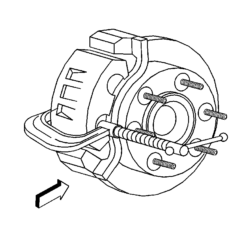
- Mark the relationship of the hub to the rotor.
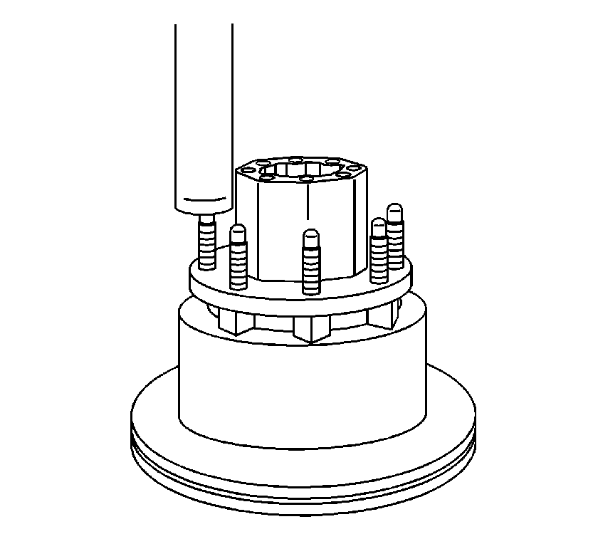
- Place the hub and rotor assembly on a hydraulic press.
- Press the wheel studs out of the hub and rotor assembly.
Installation Procedure
- Align the hub and the rotor (if applicable).
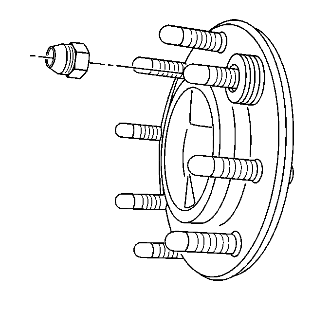
- Install each of the new wheel studs into the hub and rotor assembly by performing the following steps:
| 2.2. | Install 4 washers to the stud. |
| 2.3. | Install a lug nut to the stud with the flat side of the nut towards the washers. |
| 2.4. | Tighten the lug nut to draw the stud into the hub and rotor assembly. |
| 2.5. | Inspect the hub and rotor assembly to ensure that the hub is tight against the rotor and the stud is seated completely. |
| 2.6. | Remove the lug nut and the washers. |
- Install the hub and rotor assembly to the vehicle. Refer to
Rear Axle Hub, Bearing, Cup, and/or Seal Replacement.
- Install the tire and wheel assembly. Refer to
Tire and Wheel Removal and Installation.
- Lower the vehicle.
- With the engine OFF, gradually apply the brake pedal to approximately 2/3 of its travel distance.
- Slowly release the brake pedal.
- Wait 15 seconds, then repeat steps 6-7 until a firm pedal is obtained. This will properly seat the brake caliper pistons and brake pads.
- Fill the master cylinder reservoir to the proper level with clean brake fluid. Refer to
Master Cylinder Reservoir Filling.
- 24. If the brake rotor was refinished, replaced, or if new disc brake pads were installed, burnish the pads and rotors. Refer to
Brake Pad and Rotor Burnishing.
Rear Brake Rotor Replacement Except Dual Wheels or NYS
Tools Required
Caution: Refer to Brake Dust Caution in the Preface section.
Notice: Any new rotor must have the protective coating removed from the friction surfaces before being placed in service. Remove the protective coating using
denatured alcohol or an equivalent brake cleaner, and wipe the surface clean with clean cloths. Do not use gasoline, kerosene, or other oil base solvents which may leave an oily residue. This residue is damaging to the brake lining and is flammable.
Removal Procedure
- Release the park brake.
- Raise and suitably support the vehicle. Refer to
Lifting and Jacking the Vehicle
in General Information.
- Remove the tire and wheel assembly. Refer to
Tire and Wheel Removal and Installation
in Tires and Wheels.
- Mark the relationship of the rotor to the hub.
- Install a C-clamp over the body of the brake caliper, with the C-clamp ends against the rear of the caliper body and the outboard disc brake pad.
- Slowly tighten the C-clamp until the pistons are pushed into the caliper bores enough to remove the caliper from the pads.
- Remove the C-clamp from the caliper.
- Remove the brake caliper bracket mounting bolts.
Notice: Support the brake caliper with heavy mechanic wire, or equivalent,
whenever it is separated from its mount and the hydraulic flexible brake hose is still connected. Failure to support the caliper in this manner will cause the flexible brake hose to bear the weight of the caliper, which may cause damage to the brake hose and
in turn may cause a brake fluid leak.
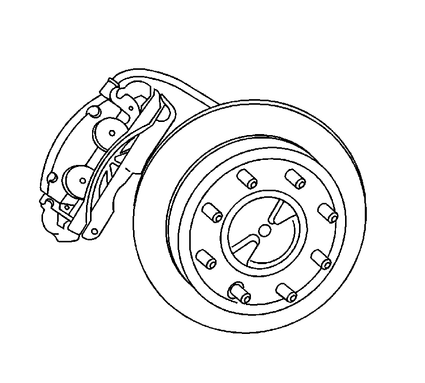
- Remove the brake caliper and brake caliper bracket as an assembly and support with heavy mechanic's wire or equivalent. DO NOT disconnect the hydraulic brake flexible hose from the caliper.
- Remove the rotor retaining push nuts from the wheel studs, if applicable.
- It may be necessary to strike the end of the hub or the rotor with a deadblow hammer to separate the rotor from the hub.
- Remove the brake rotor. Do not force the rotor off. If the rotor is difficult to remove, ease it off by gently rotating it as you
pull outward.
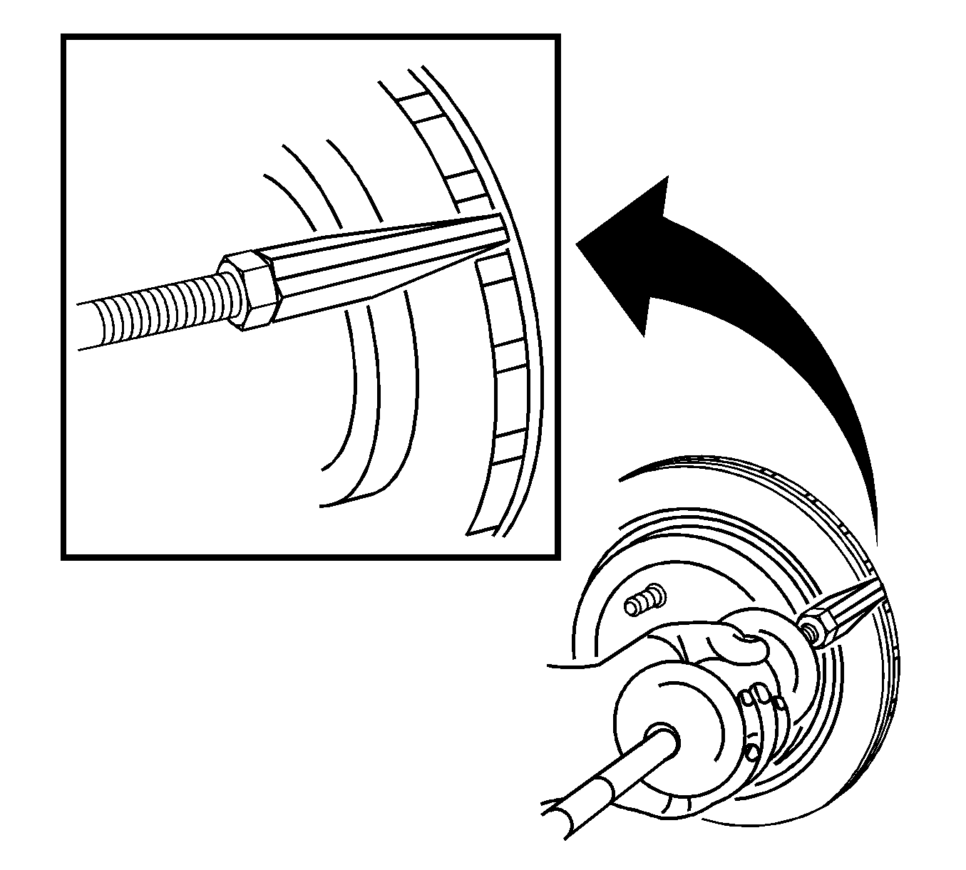
- If the brake rotor cannot be removed perform the following:
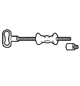
| 13.2. | Insert
J-46277
between the rotor friction surfaces in the vent section of the rotor. |
DO NOT place the
J-46277
on the rotor friction
surface.
| 13.4. | Inspect the park brake components for the following conditions: |
| • | Bent or broken hold down spring |
| • | Broken, cracked or worn brake shoe lining |
| • | Bent or damaged brake shoe |
| • | Worn, bent or damaged backing plate |
| 13.5. | If any of these conditions are found replace the affected parts. |
Installation Procedure
Important: Whenever the brake rotor has been separated from the hub/axle flange, any rust or contaminants should be cleaned from the hub/axle flange and the brake rotor mating surfaces. Failure to do this may result in excessive
assembled lateral runout (LRO) of the brake rotor, which could lead to brake pulsation.
- Use the
J 42450-A
to clean all rust and contaminants from the mating surface of the hub flange.
- Use the
J 41013
to clean all rust and contaminants from the inside diameter of the hat section of the brake rotor to prevent any foreign material from getting between the brake rotor and the
hub flange.
- Inspect the mating surfaces of the hub/axle flange and the rotor to ensure that there are no foreign particles or debris remaining.
- Align the rotor to its original position on the hub, if applicable, and install the rotor.
- If the brake rotor was removed and installed as part of a brake system repair, measure the assembled lateral runout (LRO) of the brake rotor to ensure optimum performance of the disc brakes. Refer to
Brake Rotor Assembled Lateral Runout Measurement
.
- If the brake rotor assembled LRO measurement exceeds the specification, bring the LRO to within specifications. Refer to
Brake Rotor Assembled Lateral Runout Correction
.
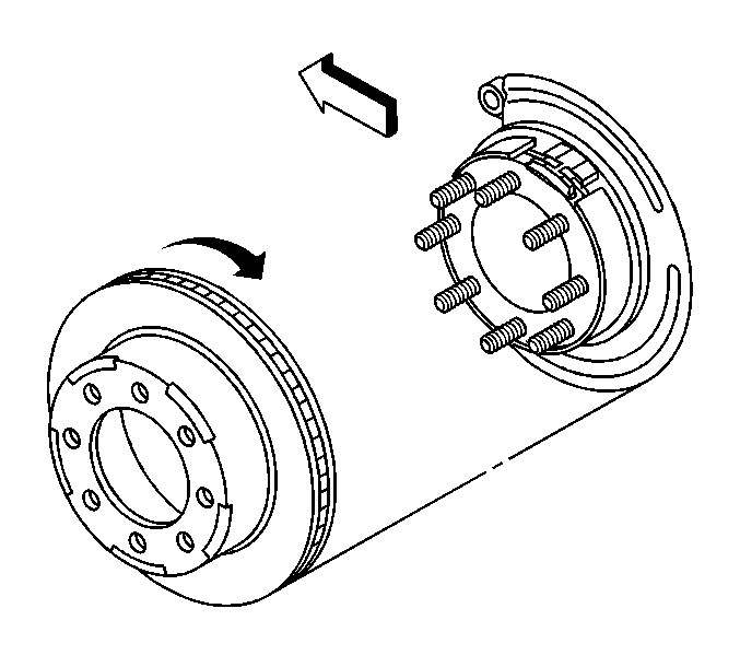
- Install the rotor by slowly turning the rotor while pushing the rotor towards the axle.
- Install the caliper and the bracket as an assembly to the vehicle.
- Perform the following procedure before installing the caliper bracket mounting bolts.
| 9.1. | Remove all traces of the original adhesive patch. |
| 9.2. | Clean the threads of the bolt with brake parts cleaner or the equivalent and allow to dry. |
| 9.3. | Apply Threadlocker GM P/N 12345493 (Canadian P/N 10953488) to the threads of the bolt. |
Notice: Use the correct fastener in the correct location. Replacement fasteners
must be the correct part number for that application. Fasteners requiring
replacement or fasteners requiring the use of thread locking compound or sealant
are identified in the service procedure. Do not use paints, lubricants, or
corrosion inhibitors on fasteners or fastener joint surfaces unless specified.
These coatings affect fastener torque and joint clamping force and may damage
the fastener. Use the correct tightening sequence and specifications when
installing fasteners in order to avoid damage to parts and systems.
- Install the caliper bracket mounting bolts.
Tighten
| • | For the 15 series, tighten the brake caliper bracket mounting bolts to 200 N·m (148 lb ft). |
| • | For the 25/35 series, tighten the brake caliper bracket mounting bolts to 165 N·m (122 lb ft). |
- Install the tire and wheel assembly. Refer to
Tire and Wheel Removal and Installation
in Tires and Wheels.
- Lower the vehicle.
- With the engine OFF, gradually apply the brake pedal to approximately 2/3 of it's travel distance.
- Slowly release the brake pedal.
- Wait 15 seconds, then repeat steps 13-14 until a firm pedal is obtained. This will properly seat the brake caliper pistons and brake pads.
- Fill the master cylinder reservoir to the proper level with clean brake fluid. Refer to
Master Cylinder Reservoir Filling
in Hydraulic Brakes.
Rear Brake Rotor Replacement W/NYS
Tools Required
Caution: Refer to Brake Dust Caution in the Preface section.
Notice: Any new rotor must have the protective coating removed from the friction surfaces before being placed in service. Remove the protective coating using
denatured alcohol or an equivalent brake cleaner, and wipe the surface clean with clean cloths. Do not use gasoline, kerosene, or other oil base solvents which may leave an oily residue. This residue is damaging to the brake lining and is flammable.
Removal Procedure
- Release the park brake.
- Raise and suitably support the vehicle. Refer to
Lifting and Jacking the Vehicle
in General Information.
- Remove the tire and wheel assembly. Refer to
Tire and Wheel Removal and Installation
in Tires and Wheels.
- Mark the relationship of the rotor to the hub.
- Install a C-clamp over the body of the brake caliper, with the C-clamp ends against the rear of the caliper body and the outboard disc brake pad.
- Slowly tighten the C-clamp until the pistons are pushed into the caliper bores enough to remove the caliper from the pads.
- Remove the C-clamp from the caliper.
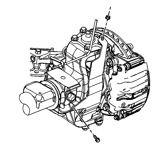
- Remove the nut and the bolt from the quarter shaft shield.
- Remove the shield.
- Remove the 2 brake caliper bracket mounting bolts.
- Mark the relationship of the rotor to the hub.
Notice: Support the brake caliper with heavy mechanic wire, or equivalent,
whenever it is separated from its mount and the hydraulic flexible brake hose is still connected. Failure to support the caliper in this manner will cause the flexible brake hose to bear the weight of the caliper, which may cause damage to the brake hose and
in turn may cause a brake fluid leak.
- Remove the brake caliper and brake caliper mounting bracket as an assembly and support with heavy mechanic's wire or equivalent. DO NOT disconnect the hydraulic brake flexible hose from the caliper.
- Remove the rotor retaining push nuts from the wheel studs, if applicable.
- It may be necessary to strike the end of the hub or the rotor with a deadblow hammer to separate the rotor from the hub.
- Remove the rotor by slowly turning the rotor while pulling the rotor away from the axle.
Installation Procedure
Important: Whenever the brake rotor has been separated from the hub/axle flange, any rust or contaminants should be cleaned from the hub/axle flange and the brake rotor mating surfaces. Failure to do this may result in excessive
assembled lateral runout (LRO) of the brake rotor, which could lead to brake pulsation.
- Use the
J 42450-A
to clean all rust and contaminants from the mating surface of the hub flange.
- Use the
J 41013
to clean all rust and contaminants from the inside diameter of the hat section of the brake rotor to prevent any foreign material from getting between the brake rotor
and the hub flange.
- Inspect the mating surfaces of the hub/axle flange and the rotor to ensure that there are no foreign particles or debris remaining.
- Align the rotor to its original position on the hub, if applicable.
- Install the rotor by slowly turning the rotor while pushing the rotor towards the axle.
- If the brake rotor was removed and installed as part of a brake system repair, measure the assembled lateral runout (LRO) of the brake rotor to ensure optimum performance of the disc brakes. Refer to
Brake Rotor Assembled Lateral Runout Measurement
.
- If the brake rotor assembled LRO measurement exceeds the specification, bring the LRO to within specifications. Refer to
Brake Rotor Assembled Lateral Runout Correction
.
- Install the brake caliper and the brake caliper mounting bracket as an assembly to the vehicle.
- Perform the following procedure before installing the 2 brake caliper bracket mounting bolts.
| 9.1. | Remove all traces of the original adhesive patch. |
| 9.2. | Clean the threads of the bolts with brake parts cleaner or the equivalent and allow to dry. |
| 9.3. | Apply Threadlocker GM P/N 12345493 (Canadian P/N 10953488) to the threads of the bolts. |
Notice: Use the correct fastener in the correct location. Replacement fasteners
must be the correct part number for that application. Fasteners requiring
replacement or fasteners requiring the use of thread locking compound or sealant
are identified in the service procedure. Do not use paints, lubricants, or
corrosion inhibitors on fasteners or fastener joint surfaces unless specified.
These coatings affect fastener torque and joint clamping force and may damage
the fastener. Use the correct tightening sequence and specifications when
installing fasteners in order to avoid damage to parts and systems.
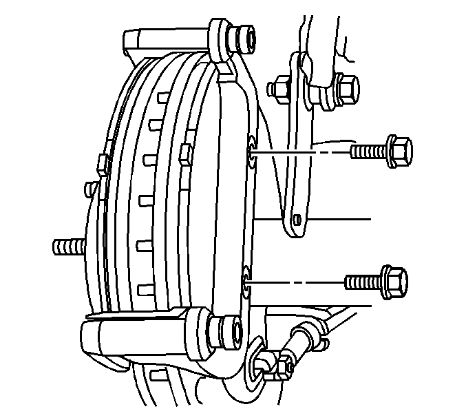
- Install the brake caliper bracket mounting bolts.
Tighten
Tighten the brake caliper bracket mounting bolts to 200 N·m (148 lb ft).
- Install the quarter shaft shield.
- Install the quarter shaft shield nut and the bolt.
Tighten
Tighten the quarter shaft shield nut and the bolt to 25 N·m (18 lb ft).
- Install the tire and wheel assembly. Refer to
Tire and Wheel Removal and Installation
in Tires and Wheels.
- Lower the vehicle.
- With the engine OFF gradually apply the brake pedal to approximately 2/3 of it's travel distance.
- Slowly release the brake pedal.
- Wait 15 seconds then repeat steps 15-16 until a firm pedal is obtained. This will properly seat the brake caliper pistons and brake pads.
