Intake Manifold Tube Replacement Federal Emissions
Removal Procedure

- Remove the turbocharger. Refer to
Turbocharger Replacement
.
- Remove the exhaust gas recirculation (EGR) valve. Refer to
Exhaust Gas Recirculation Valve Replacement
in Engine
Controls - 6.6 L.
- Disconnect the wire terminal from the intake air heater.
- Remove the following fuel pipes and wiring harnesses:
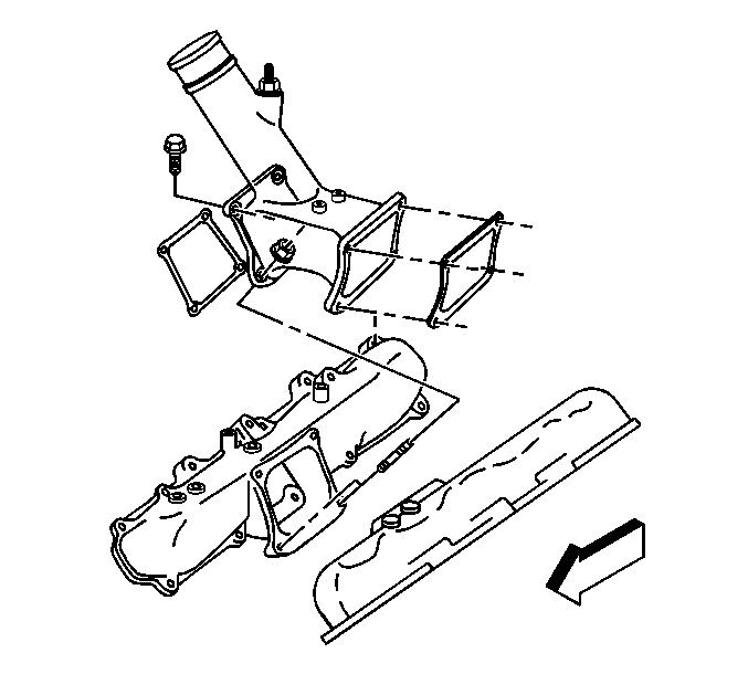
- Remove the intake manifold tube bolts/nuts.
- Pull-up the intake manifold tube in order to remove.
- Remove and discard the gaskets.
- Remove the intake air heater from the intake manifold tube, if replacing
the tube.
- Clean the intake manifold tube in cleaning solvent and air dry.
Installation Procedure

Notice: Use the correct fastener in the correct location. Replacement fasteners
must be the correct part number for that application. Fasteners requiring
replacement or fasteners requiring the use of thread locking compound or sealant
are identified in the service procedure. Do not use paints, lubricants, or
corrosion inhibitors on fasteners or fastener joint surfaces unless specified.
These coatings affect fastener torque and joint clamping force and may damage
the fastener. Use the correct tightening sequence and specifications when
installing fasteners in order to avoid damage to parts and systems.
- Install the intake air heater, if removed.
Tighten
Tighten the heater to 50 N·m (37 lb ft).
- Install the intake manifold tube with NEW gaskets.

- Install the intake manifold tube bolts/nuts.
- Tighten the intake manifold tube bolts/nuts in the order shown.
Tighten
Tighten the bolts/nuts to 9 N·m (80 lb in).
- Install the following fuel pipes and wiring harnesses:
- Install the intake air heater terminal and nut.
Tighten
Tighten the nut to 4 N·m (35 lb in).
- Install the EGR valve. Refer to
Exhaust Gas Recirculation Valve Replacement
in Engine Controls - 6.6 L.
- Install the turbocharger. Refer to
Turbocharger Replacement
.
Intake Manifold Tube Replacement California Emissions
Removal Procedure

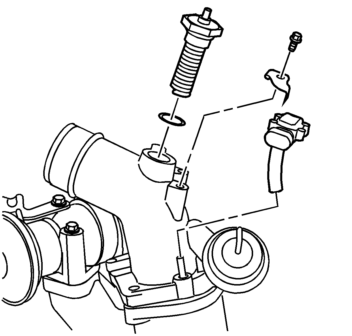
- Remove the turbocharger boost sensor bracket
bolt.
- Remove the turbocharger boost sensor with bracket.
- Remove the intake air heater nut and wire terminal from the intake air
heater.
- Remove the intake air heater and gasket, if replacing the tube.
- Remove the following fuel pipes and wiring harnesses:

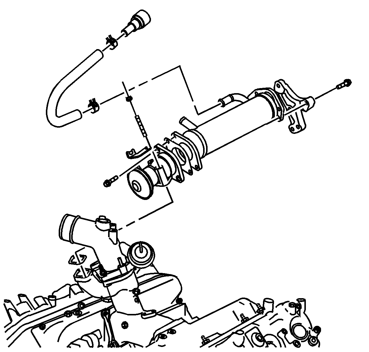
- Remove the exhaust gas recirculation (EGR)
cooling hose clamps.
- Remove the EGR cooling hose.
- Remove the EGR bolts/nuts.
- Remove the EGR cooler bracket bolts.
- Remove the EGR cooler bracket.
- Remove the EGR and cooler.

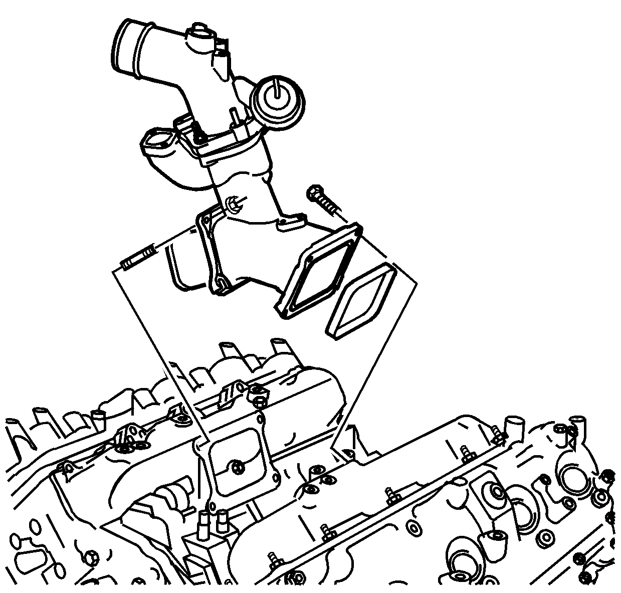
- Remove the intake manifold tube bolts/nuts.
- Remove the intake manifold tube.
- Remove and discard the gaskets.
- Clean the intake manifold tube in cleaning solvent and air dry.
Installation Procedure

- Install the intake manifold tube with NEW
gaskets.

- Install the intake manifold tube bolts/nuts.
Notice: Use the correct fastener in the correct location. Replacement fasteners
must be the correct part number for that application. Fasteners requiring
replacement or fasteners requiring the use of thread locking compound or sealant
are identified in the service procedure. Do not use paints, lubricants, or
corrosion inhibitors on fasteners or fastener joint surfaces unless specified.
These coatings affect fastener torque and joint clamping force and may damage
the fastener. Use the correct tightening sequence and specifications when
installing fasteners in order to avoid damage to parts and systems.
- Tighten the intake manifold tube bolts/nuts in the order shown.
Tighten
Tighten the bolts/nuts to 9 N·m (80 lb in).

- Install the EGR cooler bracket.
- Install the EGR and cooler.
- Install the EGR cooler bracket bolts.
- Install the EGR bolts and nuts.
Tighten
| • | Tighten the bolts to 20 N·m (15 lb ft). |
| • | Tighten the nuts to 19 N·m (14 lb ft). |
- Install the EGR cooling hose.
- Install the EGR cooling hose clamps.
- Install the following fuel pipes and wiring harnesses:

- Install the intake air heater and gasket,
if required.
Tighten
Tighten the heater to 50 N·m (37 lb ft).
- Install the intake air heater terminal and nut.
Tighten
Tighten the nut to 4 N·m (35 lb in).
- Install the turbocharger boost sensor with bracket.
- Disconnect the wire terminal to the intake air heater.
- Install the turbocharger boost sensor bracket bolt.
Tighten
Tighten the bolt to 10 N·m (89 lb in).


