For 1990-2009 cars only
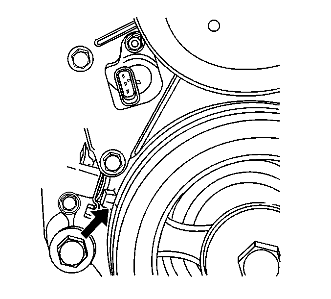
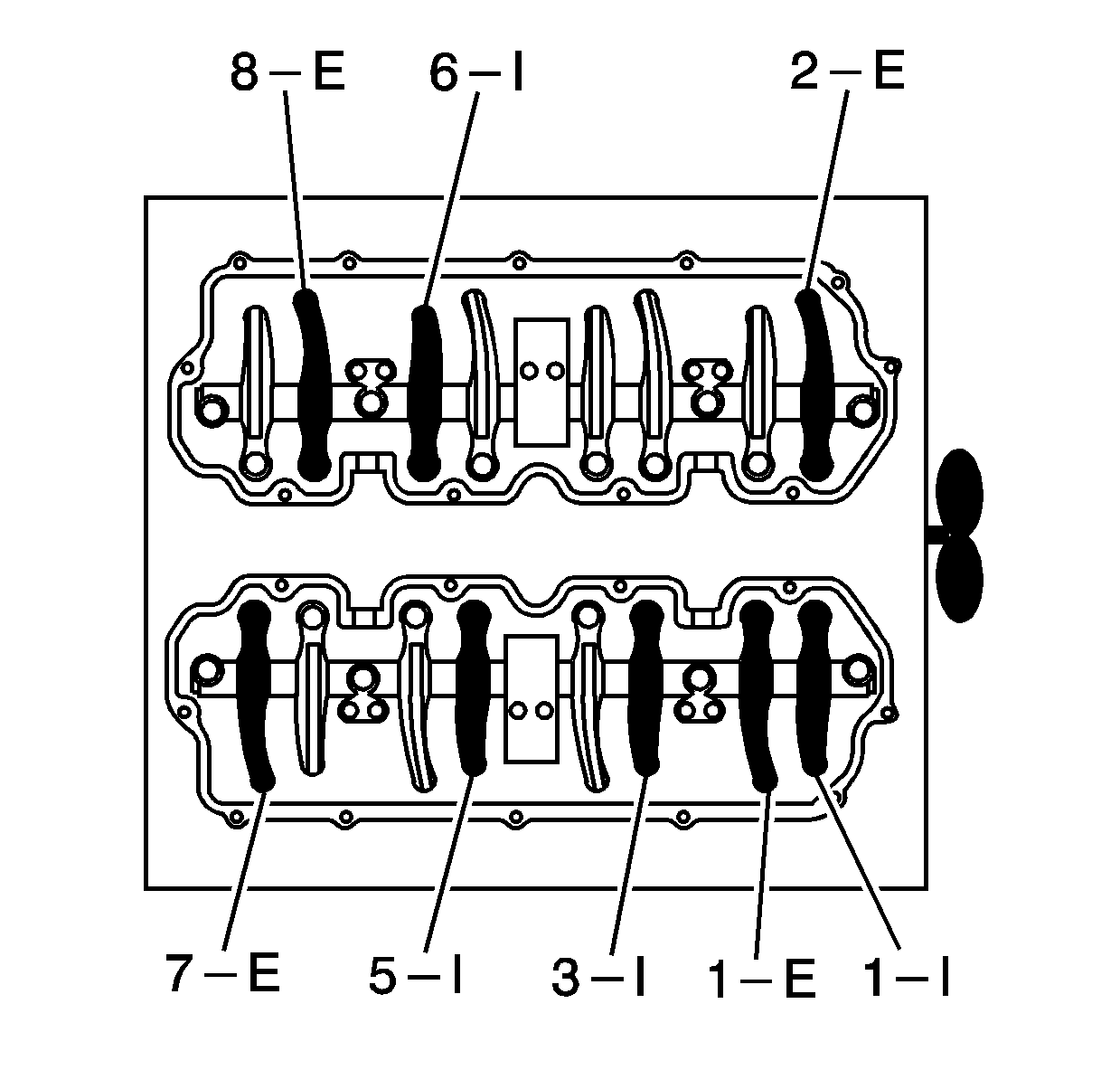
- Rotate the crankshaft to bring the number 1 cylinder at the top dead center of the compression stroke. The number 1 cylinder is the front cylinder on the right bank. The mark on the crankshaft balancer should be aligned with the mark on the engine.
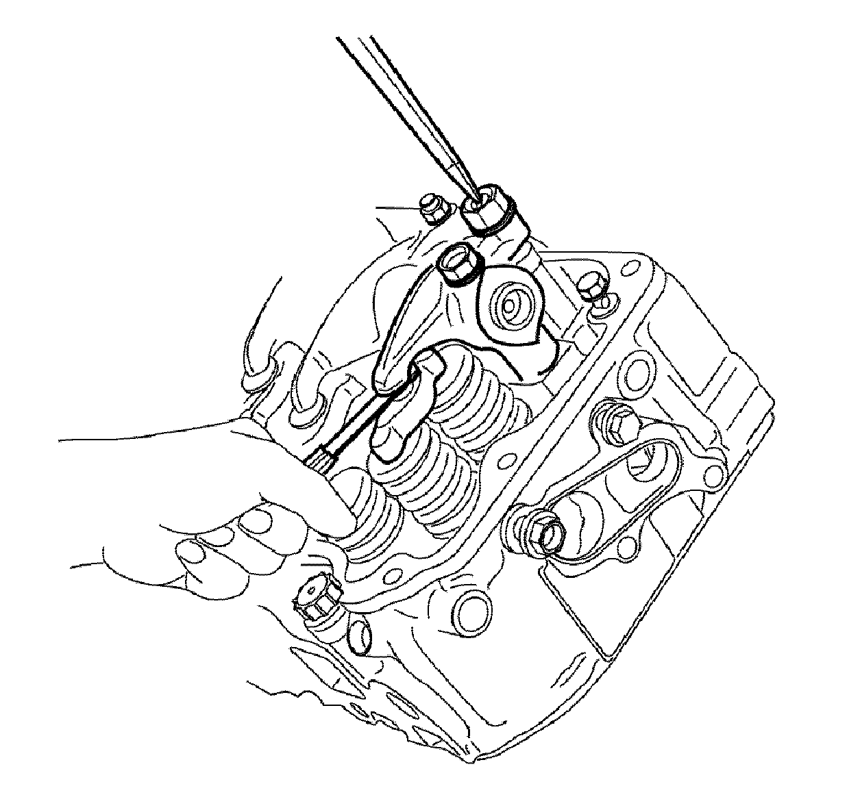
- Loosen the valve adjusting screws.
- Insert a feeler gauge between the tip of the rocker arm and the valve bridge.
- Adjust the valve lash to 0.3 mm (0.012 in). Refer to Valve Clearance Adjustment Specifications to determine which valves that can be adjusted when the engine is at Top Dead Center.
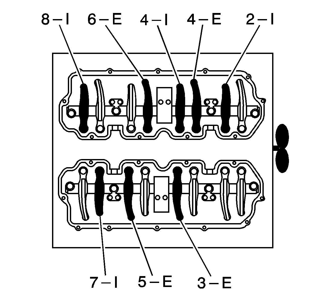
- Rotate the crankshaft one revolution to bring the number 1 cylinder at Top Dead Center of the exhaust stroke.
- Adjust the valve lash to 0.3 mm (0.012 in). Refer to Valve Clearance Adjustment Specifications to determine which valves that can be adjusted when the engine is at Top Dead Center.


Notice: Use the correct fastener in the correct location. Replacement fasteners must be the correct part number for that application. Fasteners requiring replacement or fasteners requiring the use of thread locking compound or sealant are identified in the service procedure. Do not use paints, lubricants, or corrosion inhibitors on fasteners or fastener joint surfaces unless specified. These coatings affect fastener torque and joint clamping force and may damage the fastener. Use the correct tightening sequence and specifications when installing fasteners in order to avoid damage to parts and systems.
Tighten
Tighten the valve lash lock nut to 22 N·m (16 lb ft).


Tighten
Tighten the valve lash lock nut to 22 N·m (16 lb ft).
