Intake Air Heater Relay Replacement Federal
Removal Procedure
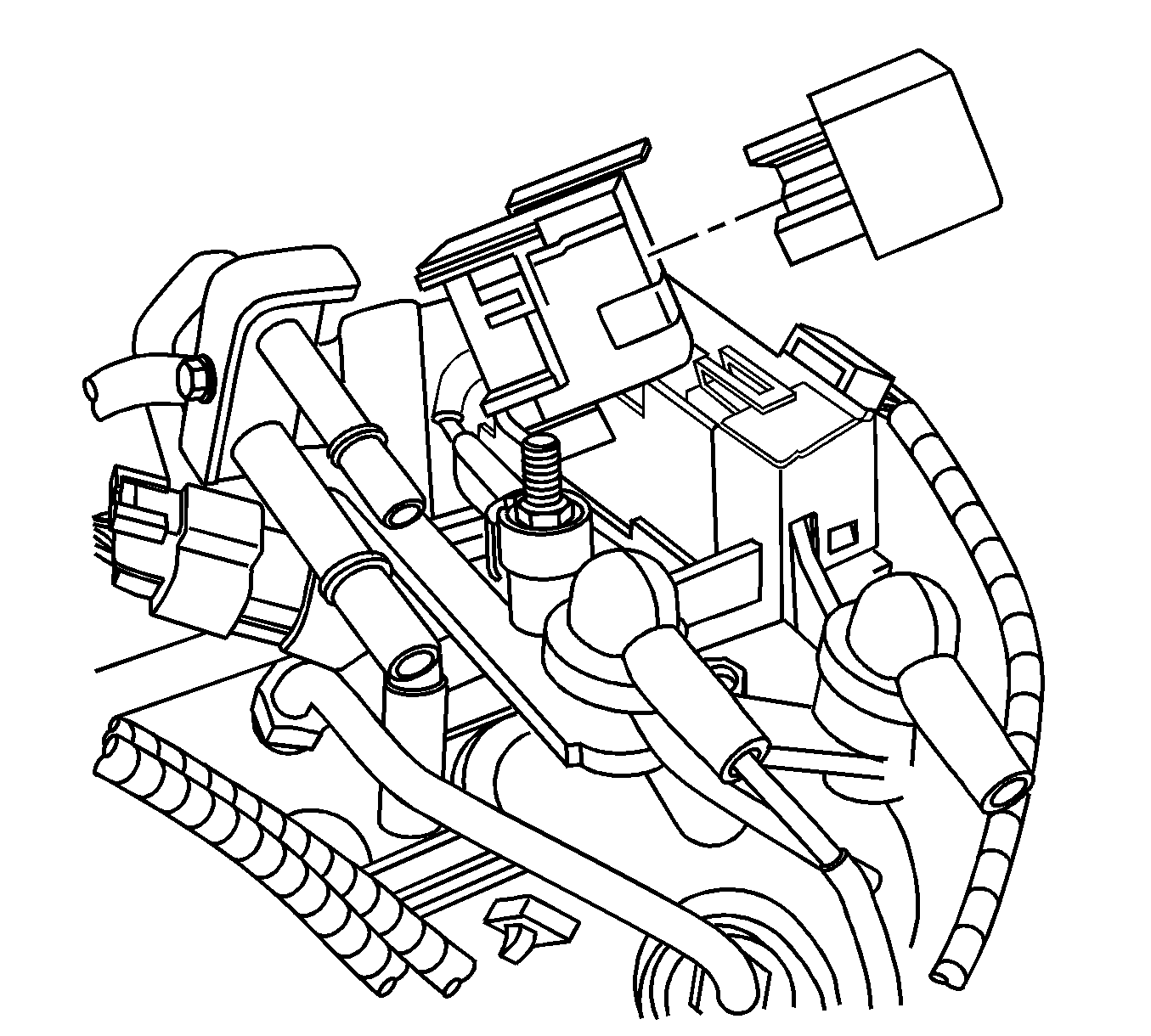
Important: The intake air heater (IAH) relay is a part of the glow plug controller on vehicles equipped with federal emissions.
- Disconnect the negative battery cable. Refer to Battery Negative Cable Disconnection and Connection in Engine Electrical.
- Remove the upper intake manifold sight shield using the following procedure:
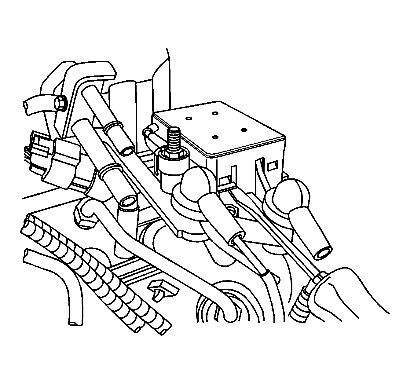
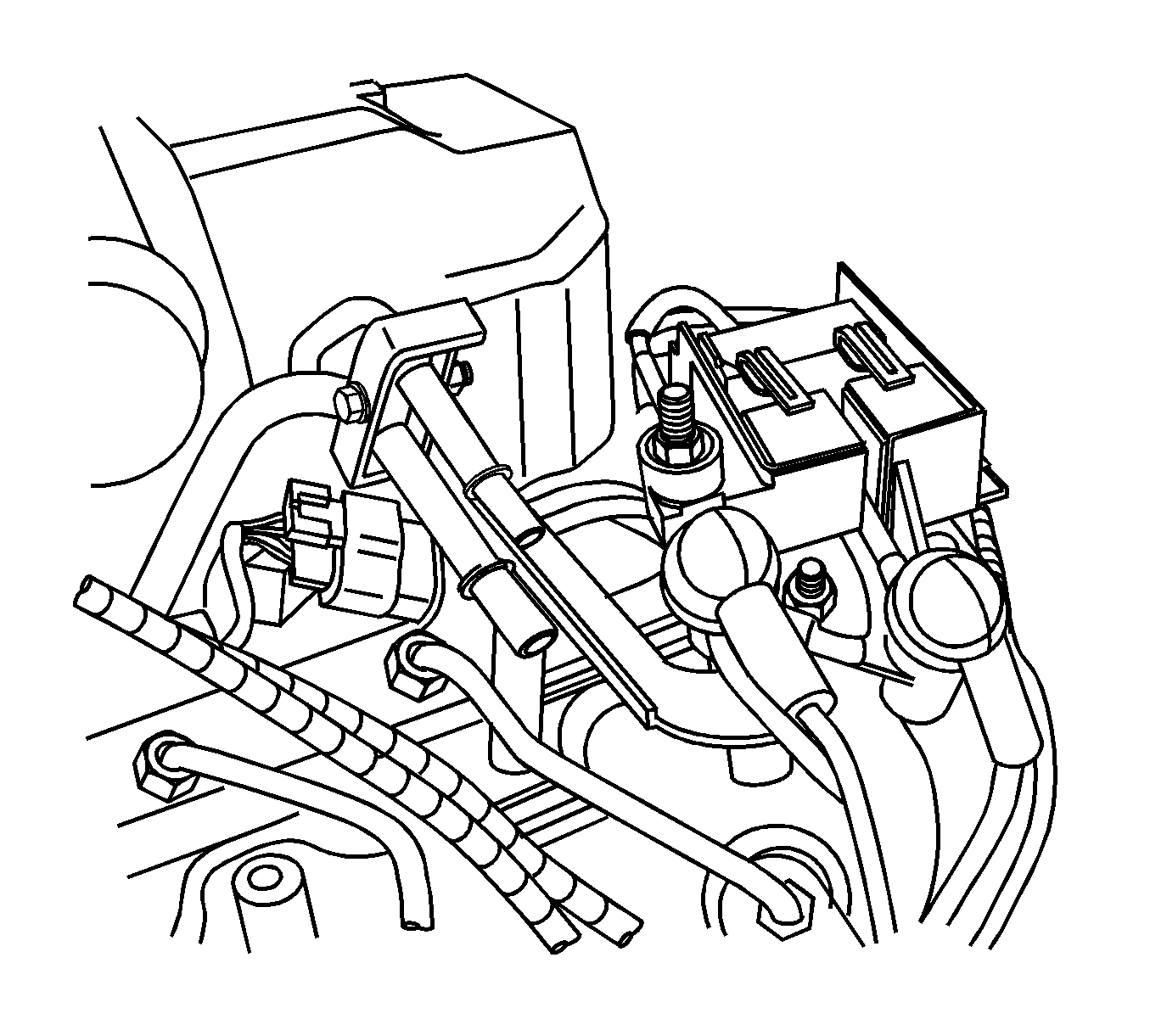
- Using a flat bladed screwdriver, disengage the glow plug controller cover clips.
- Remove the glow plug controller cover.
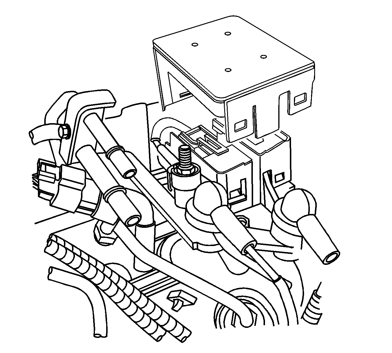
- Remove the glow plug controller nuts.
- Lift the glow plug controller off the studs.
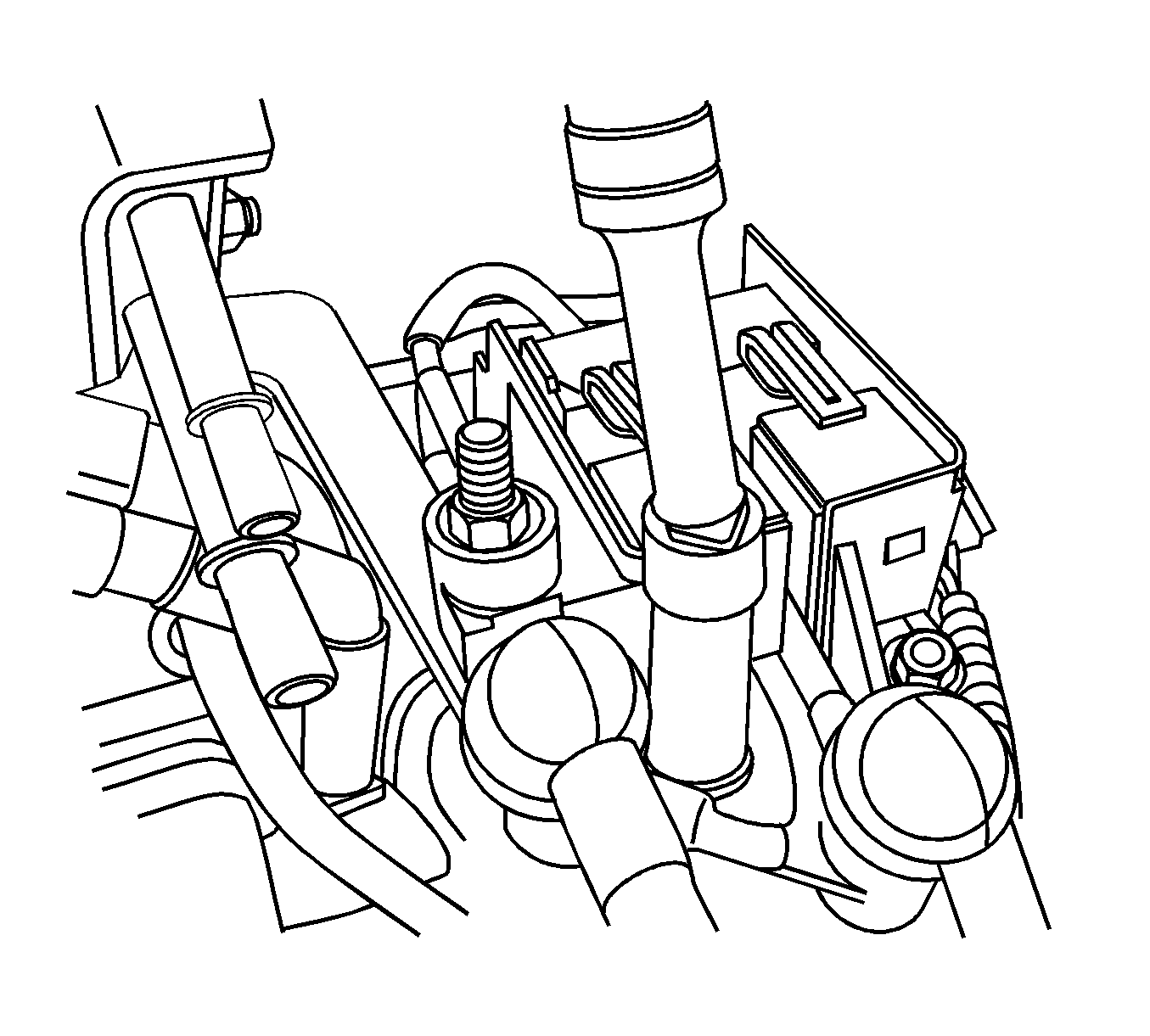
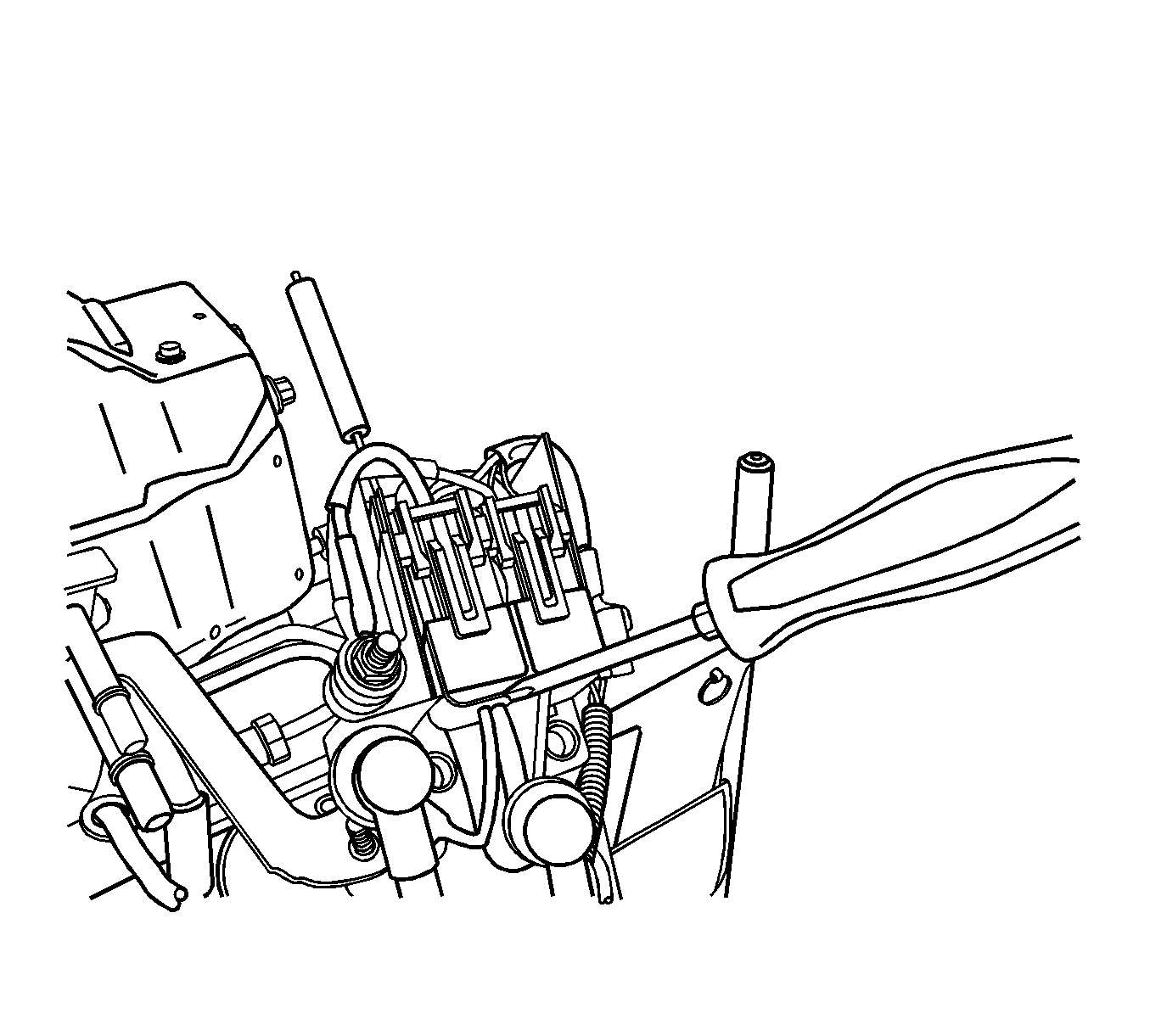
- Separate the intake heater relay from the glow plug controller housing by inserting a small screwdriver between them while prying the relay assembly outward.
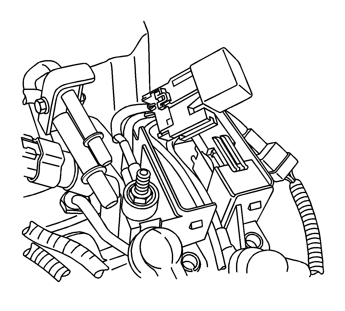
- Slide the intake heater relay outward to disengage it from the glow plug controller housing.
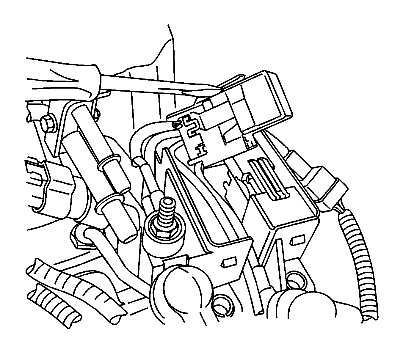
- Using a flat bladed screwdriver, disengage the intake heater relay clip.
- Remove the intake heater relay.
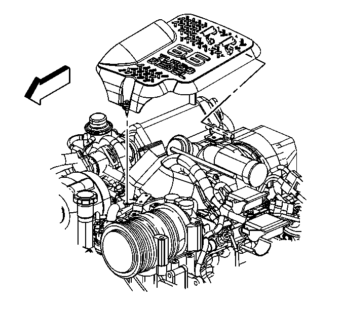
| 2.1. | Remove the retaining bolt in the front of the shield. |
| 2.2. | Lift up on the front of the shield. |
| 2.3. | Lift the shield off the rear bracket. |
Installation Procedure
- Install the intake heater relay.
- Slide the intake heater relay inward to engage it to the glow plug controller housing.
- Place the glow plug controller onto the studs.
- Install the glow plug controller nuts.
- Install the glow plug controller cover.
- Install the upper intake manifold sight shield.
- Connect the negative battery cable. Refer to Battery Negative Cable Disconnection and Connection in Engine Electrical.


Notice: Use the correct fastener in the correct location. Replacement fasteners must be the correct part number for that application. Fasteners requiring replacement or fasteners requiring the use of thread locking compound or sealant are identified in the service procedure. Do not use paints, lubricants, or corrosion inhibitors on fasteners or fastener joint surfaces unless specified. These coatings affect fastener torque and joint clamping force and may damage the fastener. Use the correct tightening sequence and specifications when installing fasteners in order to avoid damage to parts and systems.
Tighten
Tighten the nuts to 42 N·m (31 lb ft).


Tighten
Tighten the bolt to 9 N·m (80 lb in).
Intake Air Heater Relay Replacement California
Removal Procedure
- Disconnect the negative battery cable. Refer to Battery Negative Cable Disconnection and Connection in Engine Electrical.
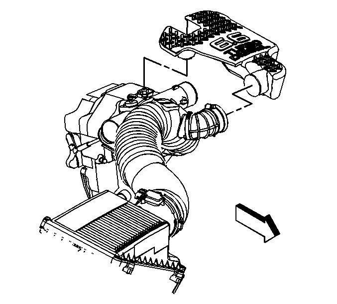
- Loosen the outlet duct clamp at the upper intake manifold cover.
- Remove he upper intake manifold cover from the outlet duct.
- Remove the upper intake manifold cover.
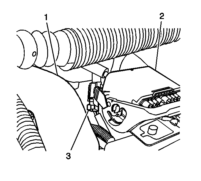
- Disconnect the engine harness electrical connector (2).
- Disconnect the intake air heater (IAH) relay electrical connector (3)
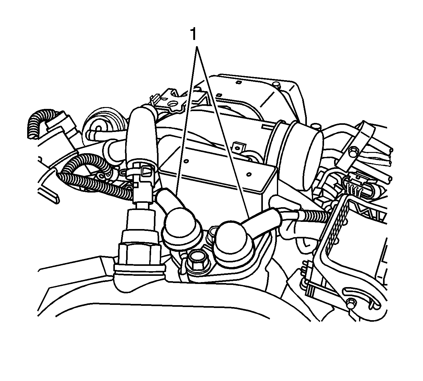
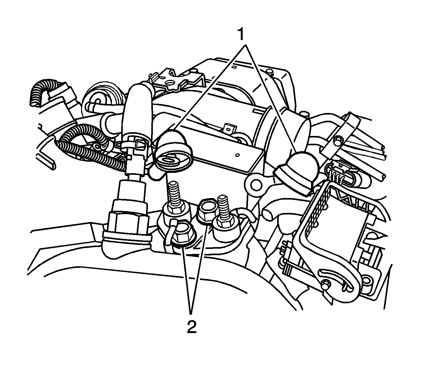
- Reposition the battery cable boots (1).
- Remove the battery cable nuts and cables from the IAH relay controller. Reposition the cables.
- Remove the IAH relay controller bolts (2).
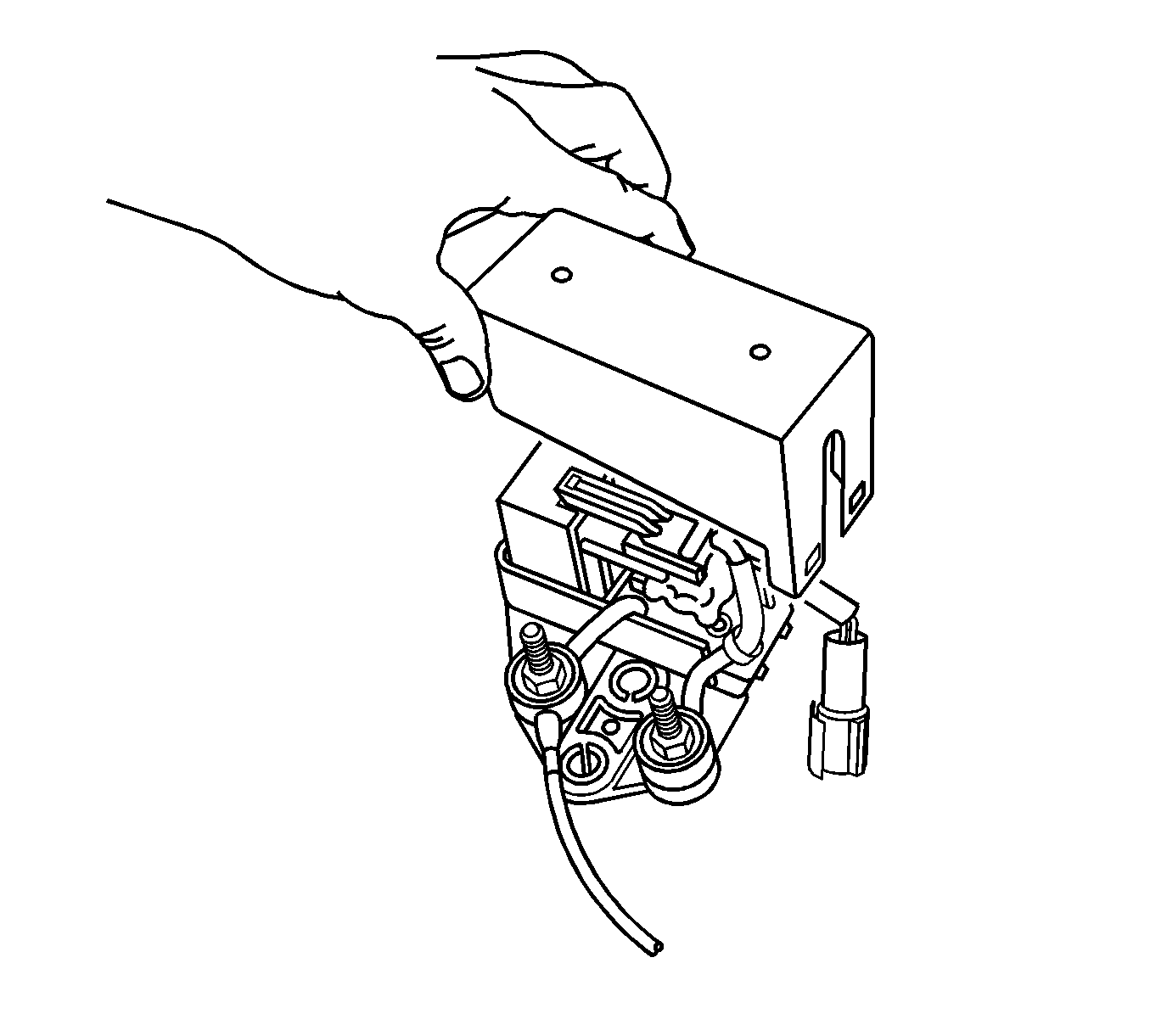
- Remove the IAH relay controller.
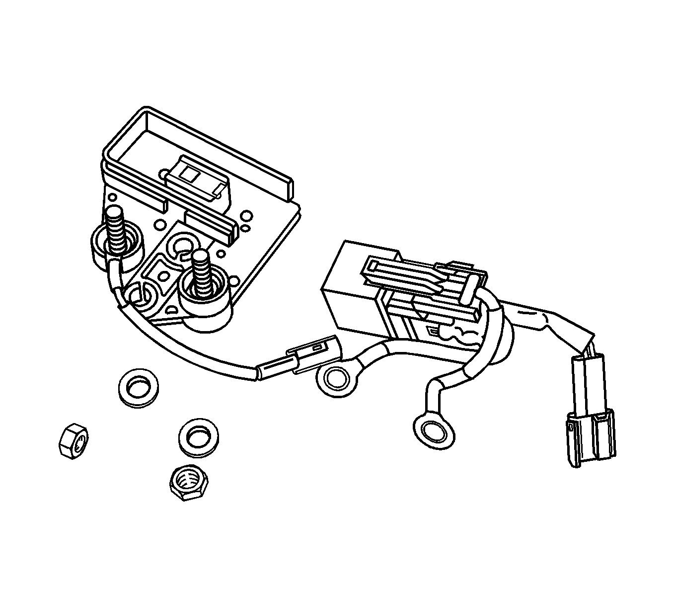
- Remove the IAH relay controller cover.
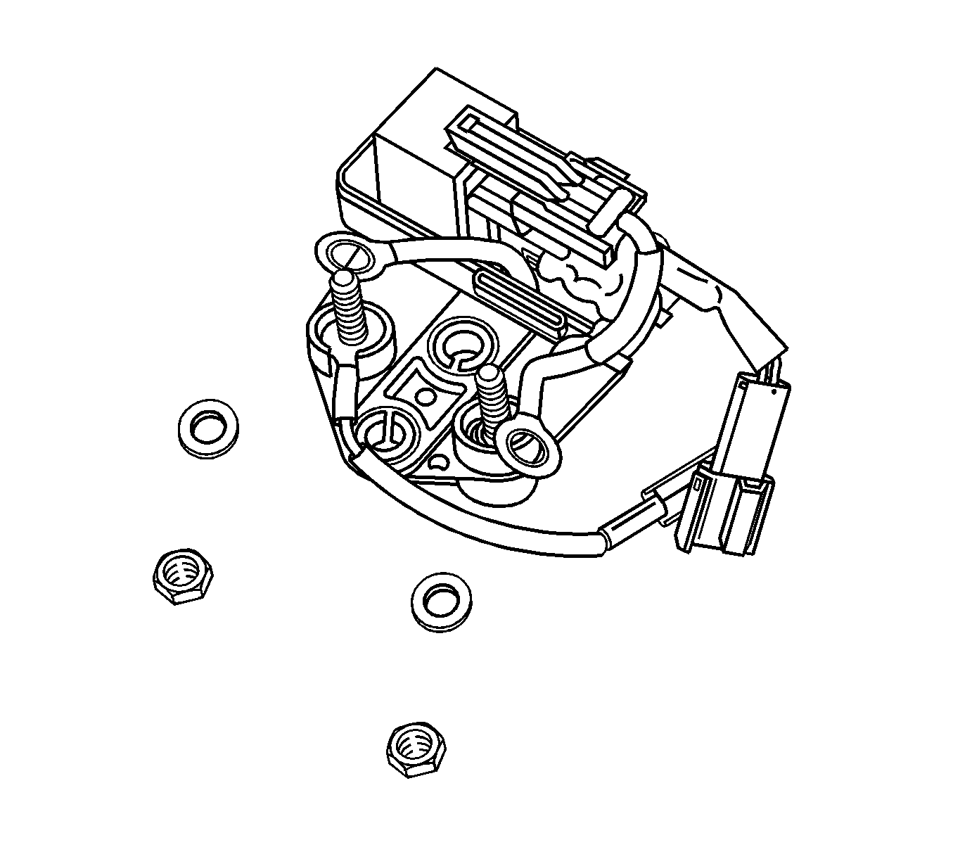
- Remove the IAH relay controller nuts and washers.
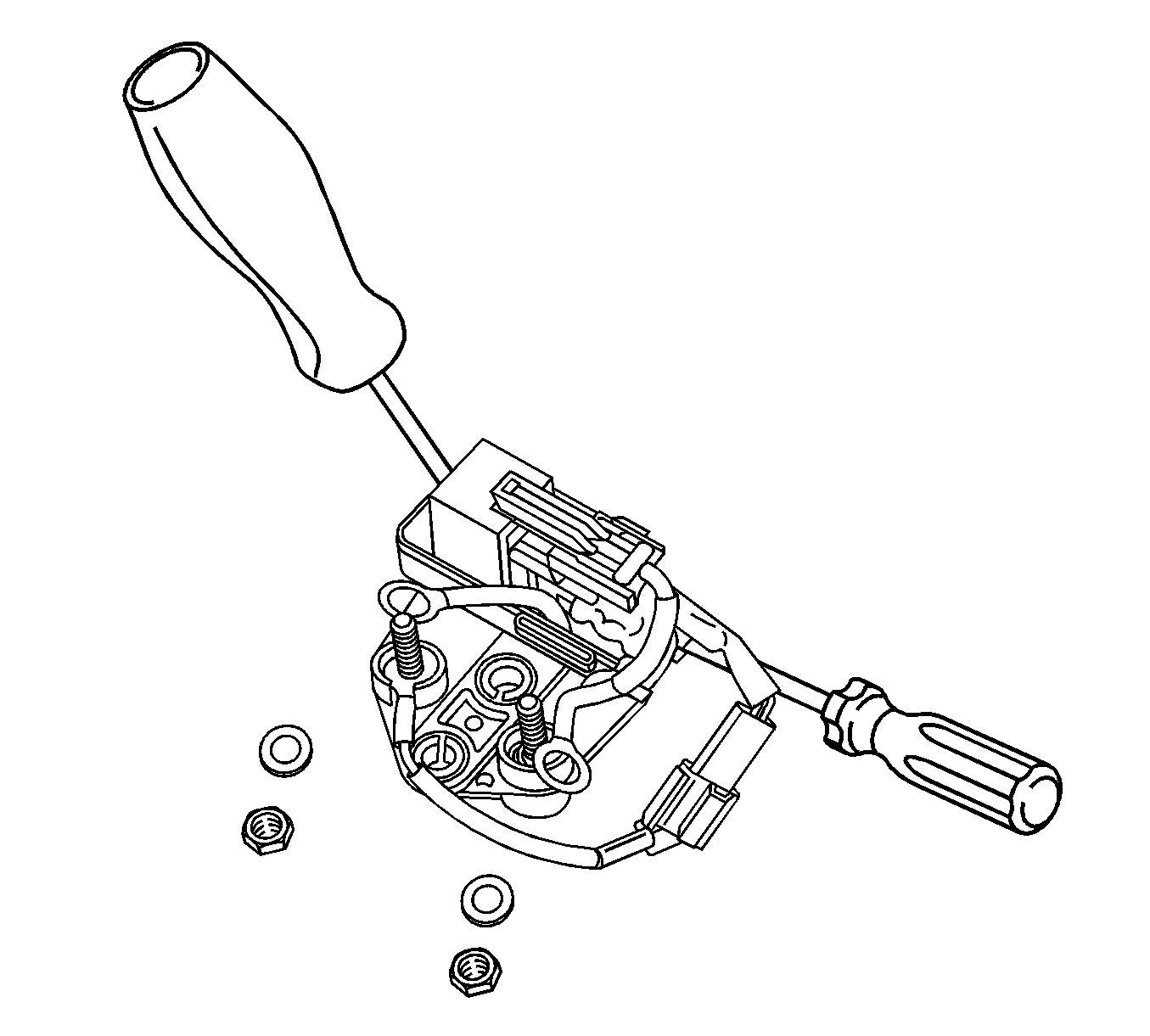
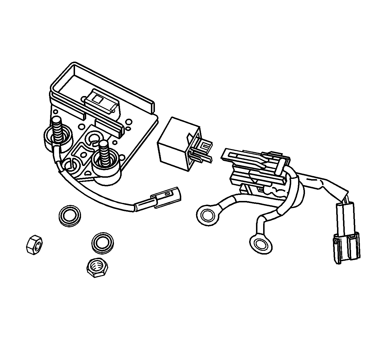
- Using 2 screwdrivers, disengage the IAH relay assembly from the controller housing.
- Remove the IAH relay assembly from the housing.
- Remove the IAH relay.
Installation Procedure
- Install the IAH relay.
- Install the IAH relay assembly to the housing.
- Install the IAH relay controller nuts and washers.
- Install the IAH relay controller cover.
- Install the IAH relay controller.
- Install the IAH relay controller bolts (2).
- Install the battery cables and nuts to the IAH relay controller.
- Reposition the battery cable boots (1).
- Connect the IAH relay electrical connector (3).
- Connect the engine harness connector (2).
- Install the upper intake manifold cover.
- Install the upper intake manifold cover to the outlet duct.
- Tighten the outlet duct clamp at the upper intake manifold cover.
- Connect the negative battery cable. Refer to Battery Negative Cable Disconnection and Connection in Engine Electrical.


Notice: Use the correct fastener in the correct location. Replacement fasteners must be the correct part number for that application. Fasteners requiring replacement or fasteners requiring the use of thread locking compound or sealant are identified in the service procedure. Do not use paints, lubricants, or corrosion inhibitors on fasteners or fastener joint surfaces unless specified. These coatings affect fastener torque and joint clamping force and may damage the fastener. Use the correct tightening sequence and specifications when installing fasteners in order to avoid damage to parts and systems.
Tighten
Tighten the nuts to 5 N·m (44 lb in).


Tighten
Tighten the bolts to 20 N·m (15 lb ft).
Tighten
Tighten the nuts to 5 N·m (44 lb in).


Tighten
Tighten the clamp to 6 N·m (53 lb in).
