For 1990-2009 cars only
Removal Procedure
- Disconnect the negative battery cables from both batteries.
- Drain the coolant. Refer to Cooling System Draining and Filling .
- Remove the upper radiator hose and two hose clamps.
- Remove the bolt holding the positive battery cable junction box and bracket and move it out of the way.
- Remove the turbo charged air outlet hose.
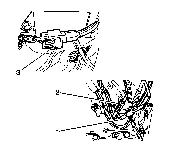
- Disconnect the 3 glow plug relay connectors (1, 2, 3).
- Remove the glow plug bracket.
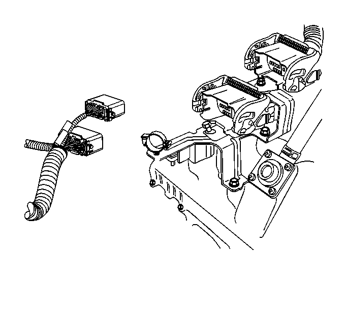
- Disconnect both 40 pin and 24 pin engine connectors.
- Remove the engine connector bracket and set aside.
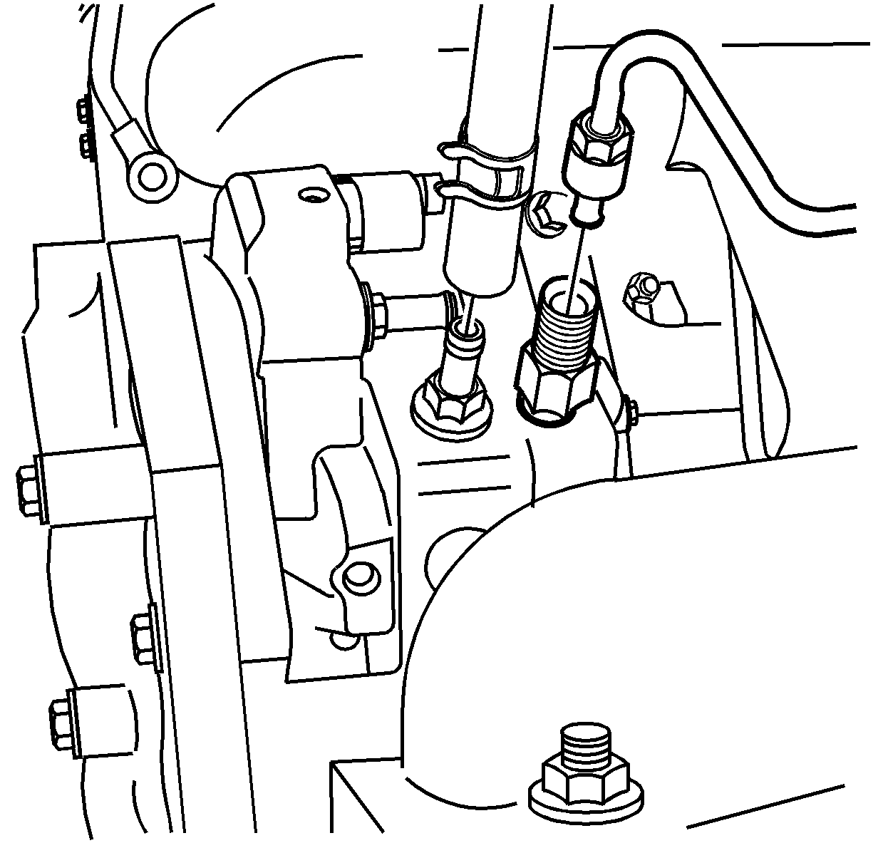
- Disconnect the fuel in-line and return lines.
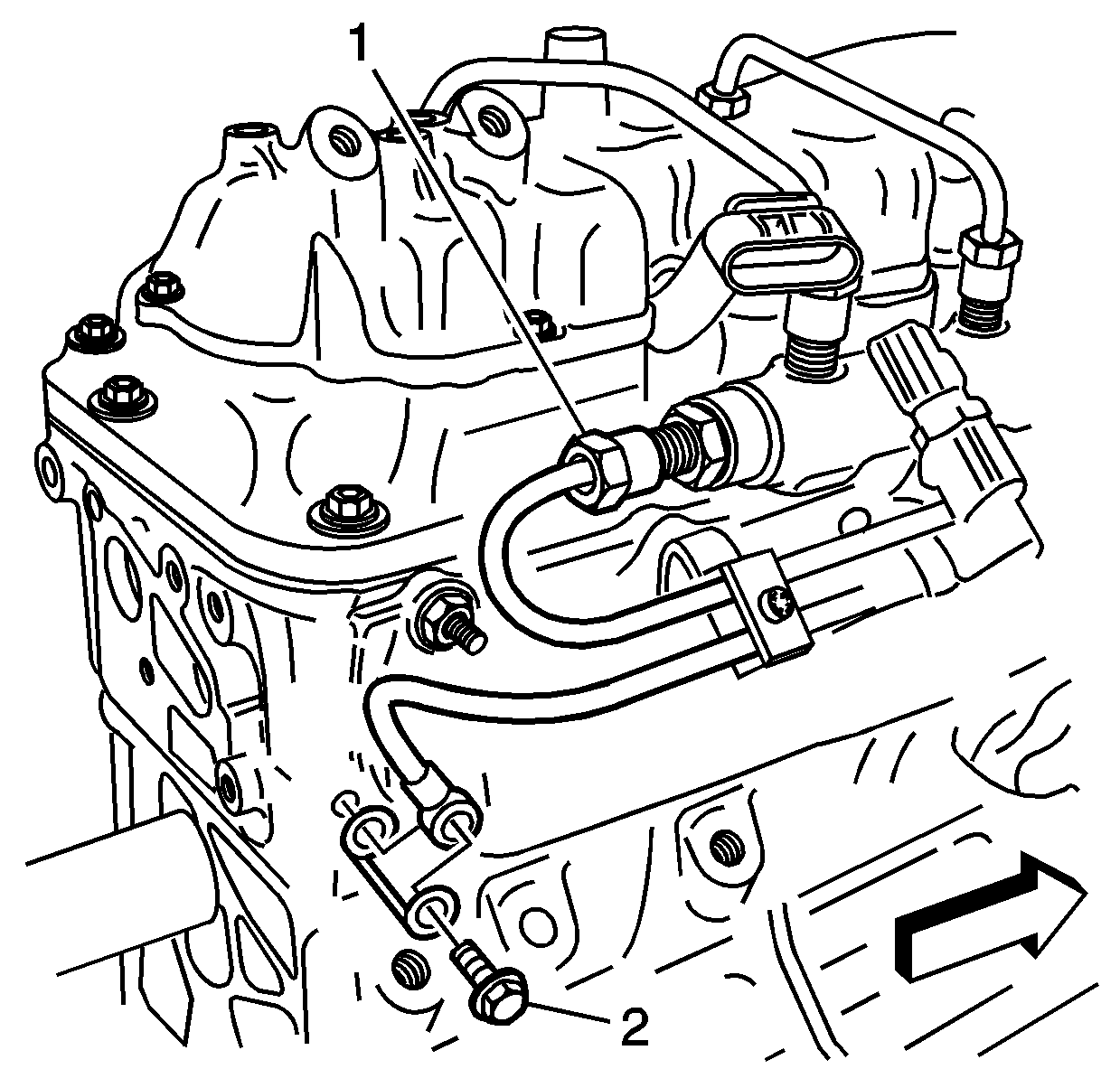
- Remove the L-bracket holding the fuel lines.
- Remove the positive crankcase ventilation (PCV) hose and clamp and move out of the way.
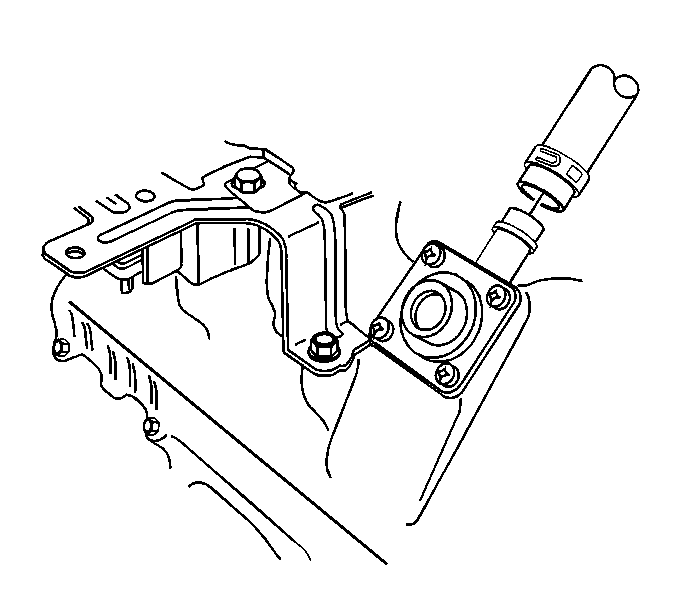
- Remove the water pipe outlet from the thermostat housing.
- Remove the serpentine belt.
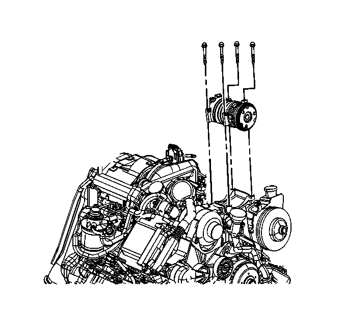
- Remove the bolts holding the air conditioning compressor and flip the unit aside.
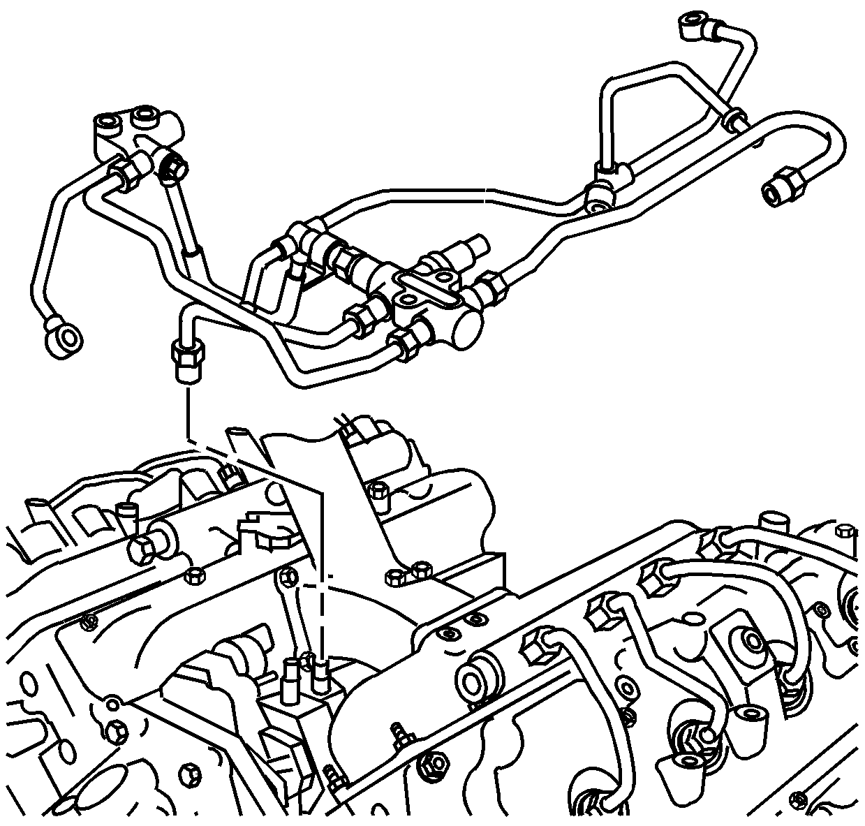
- Remove the line from the junction block to the injection pump.
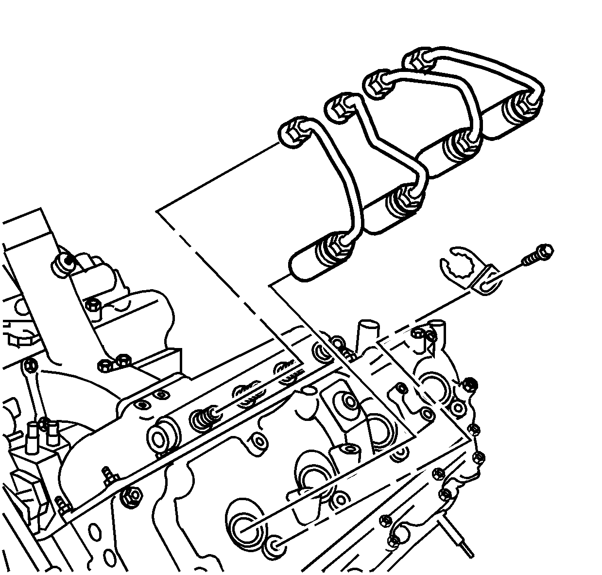
- Loosen the high pressure line (1) at the back end of the fuel rail and remove.
- Remove the junction block assembly.
- Loosen the high pressure injection lines at the four injectors first.
- Loosen the high pressure injection lines at the four fittings on the fuel rail
- Mark the high pressure injection lines in order and remove them.
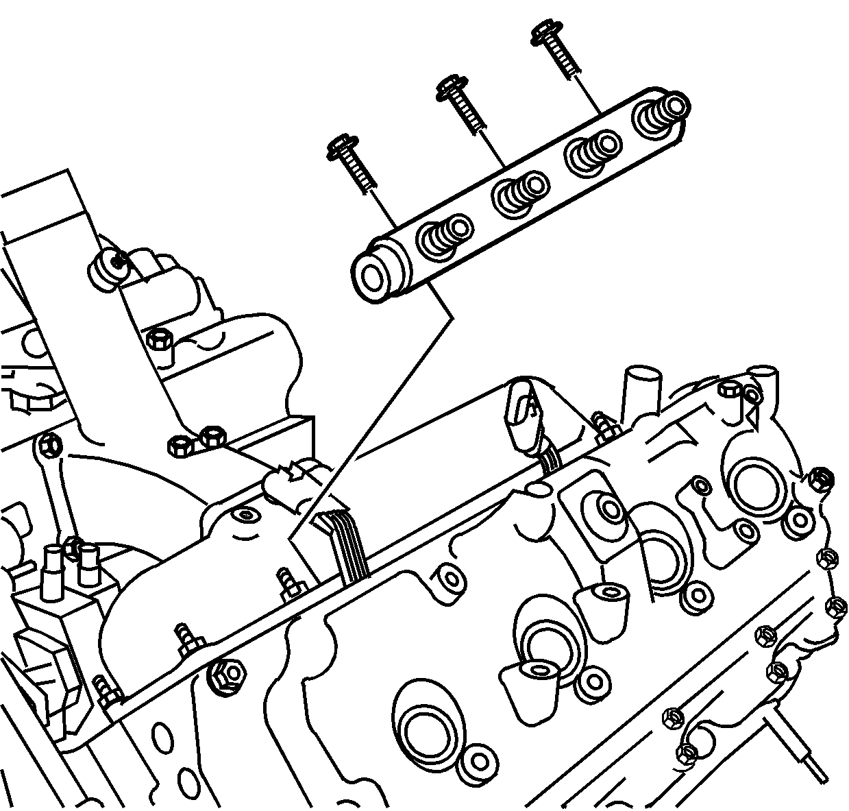
- Remove the three bolts holding the fuel rail and remove.
Caution: Refer to Battery Disconnect Caution in the Preface section.
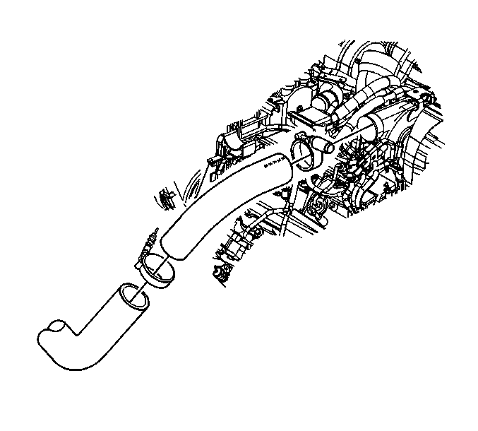
Important: Tape the turbo to keep foreign material out.
Installation Procedure
- Install the new fuel rail and bolts.
- Connect the high pressure lines between the fuel rail and injectors.
- Install the junction block assembly.
- Connect the high pressure line (1) to the back end of the fuel rail.
- Install the line from the junction block to the injection pump.
- Install the bolts holding the air conditioning compressor.
- Install drive belt. Refer to Drive Belt Replacement .
- Install the water outlet pipe to thermostat housing.
- Attach the PCV hose and clamp.
- Install the L-bracket holding the fuel lines.
- Connect the fuel lines.
- Install the glow plug bracket.
- Install the glow plug relay. Refer to Glow Plug Relay Replacement .
- Connect the connectors to the glow plug relays (1, 2, 3).
- Attach the turbo hose and clamp at the turbo to the intercooler.
- Install the bolt holding the positive battery cable junction box and bracket.
- Replace the upper radiator hose and two hose clamps.
- Replace the coolant. Refer to Cooling System Draining and Filling .
- Connect the negative battery cables to both batteries.
- Replace all hold down ties.
- Start the engine and check for leaks or noises.
- After the engine warms up, refill the coolant reservoir to the proper level.

Notice: Refer to Fastener Notice in the Preface section.

Tighten
Tighten the high pressure lines to 44 N·m (32 lb ft).


Tighten
Tighten the fuel rail bolts to 26 N·m (19 lb ft).


